CCNA: BGP CHEAT SHEET
We really want to show you why we need BGP
first but it is very difficult to explain without understanding a bit about
BGP. So we will learn some basic knowledge about BGP first.
First we need to understand about the
different between Interior Gateway Protocol and Exterior Gateway Protocol. The
difference between them is shown below:

– Interior Gateway Protocol (IGP):
A routing protocol operating within an Autonomous System (AS) like OSPF, EIGRP…
Usually routers running IGP are under the same administration (of a company,
corporation, individual)
– Exterior Gateway Protocol (EGP): A routing protocol operating between different AS. BGP is the only EGP used nowadays
– Exterior Gateway Protocol (EGP): A routing protocol operating between different AS. BGP is the only EGP used nowadays
In the topology above R1, R2 and R3 should run
an IGP to communicate with each other because they are in the same AS. But to
connect with other routers in another AS (like a different ISP), R1 and R3 must
use an EGP.
With BGP, the term autonomous
system (AS) refers to a network that operates separately from other
networks and usually operates within a single administrative domain. Each AS is
represented by an AS number. It is similar to EIGRP AS in this aspect. BGP is
used mainly by the Internet Service Provider (ISP) all over the world. Each ISP
usually has one BGP AS number (some very big ISP may have a few AS numbers).
BGP AS numbers can be between 1 to 65,535.
In the topology above R1 and R3 are operating
in BGP AS 1. If an AS connects to the public Internet using an EGP, then it
must be assigned a unique AS number which is managed by the Internet Assigned
Numbers Authority (IANA). IANA manages the AS numbers from 1 to 64,512 for
public use (similar to public IP addresses) while 64,512 to 65,535 numbers
are reserved for private use (similar to private IP addresses).
If we don’t want to show the routers inside
each AS we can simply ignore them:

In fact, the Internet that we are going
“online” everyday is a collection of interconnected autonomous systems and BGP
is running to provide routing between them.
Other BGP terms that you should learn are
listed below:
+ BGP speaker: a router running BGP
+ BGP peer or BGP neighbor: Any two routers that have formed a TCP connection to exchange BGP routing information (as BGP runs over TCP on port 179, not UDP)
+ Prefix: Maybe you learned the word “subnet”. In BGP world, it is usually called “prefix” because BGP usually does not advertise small subnets. It advertises blocks of large subnets so “prefix” is often used instead
+ Internal BGP (iBGP): refers to the BGP neighbor relationship within the same AS. The iBGP neighbor does not have to be directly connected
+ External BGP (eBGP): refers to the BGP neighbor relationship between two peers belongs to different AS. It is recommended that eBGP should be directly connected. Never run an IGP between eBGP peers.
In the below topology suppose all routers are
running BGP then R1 is considered internal BGP to R2 and R3 (as they are
running same AS 1) but is external BGP to R4. R5 is internal to R4 and R6 but external
to R3.

Why do we need BGP?
Maybe you will raise a question: “Why can’t we
only use OSPF or EIGRP instead?”
The most important reason is BGP greatly
supports path control.
Maybe you learned and understood about EIGRP,
OSPF routing protocols. They are different but both of them have the same
purpose: find the most optimal path to the destination. But when we are working
in ISP level we don’t care much about this. In ISP we really want to control
the path, even it is not the most optimal path, to the destination. For
example, how can you choose which path to go from AS 1 to AS 3 in the topology
below?

Suppose an IGP (like OSPF) is using all the
way. With default values and same bandwidth on all the links, OSPF will choose
the path AS 1 -> AS 2 -> AS 3. In order to manipulate the path we will
have to change the bandwidth of some interfaces on the edge routers of each AS.
A few months later we want to change the path then we have to configure the
bandwidth again. With BGP we can easily define the path like this: “to go from
AS 1 to AS 3 we will go through AS 2 then AS 4 then AS 5”. Moreover we can
easily control the ratio of traffic passing through each link. BGP can do this
because it has a rich set of features to control the paths to the destination.
One of the most popular features BGP uses to control the path is known as
“attributes”. However, discussion about “attributes” is out of the scope of
this tutorial, which is dedicated for CCNA learners.
In fact, BGP is a path vector protocol. Path
vector protocol does not rely on the bandwidth of the links (like OSPF) or
hop count (like RIP) or a group of parameters (like EIGRP). Path vector
protocol relies on the number of autonomous systems it has to go through. In
other words, it choose the path with least number of autonomous systems
(shortest AS Path) to reach the destination, provided that the path is
loop-free. Of course we can change the path easily for our purpose.
|
For example in the topology above, if all the
values are default and same, BGP will choose the path AS 1 -> AS 2 -> AS
3 for traffic from AS 1 destined to AS 3 because it only has to go through one
AS (AS 2).
Another reason to use BGP is BGP can
handle very big routing tables. The ISP level of routing do had large
number of routes, which IGP cannot handle. BGP handle such large routes between
AS. Currently the global Internet routing table contains over 500,000 routes.
Another good reason to use BGP is
because the great benefits of MPLS-based virtual private networks (MPLS
VPN). MPLS VPN is beyond the scope of this tutorial but in general MPLS VPN
provides traffic separation and path isolation on a shared network
infrastructure and BGP is the background layer so that VPN can operate well.
For example your corporation is running Voice over IP (VoIP), Video on Demand
(VoD), Internet service… on the same infrastructure then you can use MPLS VPN
to separate these services as if they were running on theirs own
infrastructure.
CCNA: ACCESS CONTROL LIST (ACL) CHEAT SHEET
Overview
An ACL consists of sequential series of statements known as an
Access Control Entry (ACE). Each ACE specifies a matching criteria and an
action which can be either permit or deny. The matching criteria can be various
things such as source/destination address or protocol such as TCP or UDP. For
an individual ACE all configured matching values must match in order for that
ACE to be considered as match. It recommended to include the most relevant ACE
in the beginning of the ACL. If a packet does not match any of the access
control entries in an ACL then it matches an Implicit Deny ACE that is present
at the bottom in all ACLs. The Implicit Deny ACE is a deny all statement that
denies all packets. In case this behavior is not required and packets that do
not match any ACE must be forwarded, an ACE must be specified at the bottomof
ACL that permits all packets. This type of ACE is known as explicit
permit.
A Access Control List is a multipurpose tool that is typically used as filtering tool. ACLs can be used for
_ Filtering traffic entering and existing an interface
_ Controlling access to VTY lines
_ Route update filtering
_ As a traffic classification tool when used with QoS
_ Dial-on-demand routing (DDR) with ISDN
_ Restricting output of debug commands
Types of Access-lists:
There are two types of IP Access Lists
1. Standard ACL
Traffic is filtered based on source address of the IP packet.
Since only the source address is matched, therefore, standard ACLs are
efficient in filtering traffic closet to the destination
2. Extended
Traffic can be filtered based on source address as well as
destination address and other filed in IP header including source and
destination protocol and port number, ToS and IP Precedence bits and TCP flags,
TTL value.
Numbered and Named ACLs
An ACL can be identified as either named or numbered.
Numbered standard ACLs range 1-to-99 and 1300-to-1999 and
extended ACL ranges from
100-to-199 and 2000-to-2699
ACL Rule
Only one ACL per interface, per protocol, per direction is
allowed
Inbound packets are always processed by an ACL (if applied)
before being routed.
Outbound packets are routed before processed by an ACL (if
applied)
ACLs are processed in sequential order, therefore most specific
traffic match must occur in the beginning of the ACL
Wildcard Mask
Address filtering uses wildcard masking indicate whether to
check or ignore corresponding IP address bit when comparing address bits in an
ACL entry
Wildcard masks are sometimes referred as an inverted mask
because 1 and 0 means the opposite of subnet mask.
Wildcard mask bit 0 means check the corresponding bit and 1
means ignore the corresponding bit
ACL Syntax
An ACL is implemented in two steps:define an ACL with
“access-list” or “ip access-list” command apply the ACL under specific
interface in the required direction with “ip access-group” command
STEP-1: Define an ACL
Standard ACL: Access-list acl-number {permit|deny} {host|source
source-wildcard|any}
Extended ACL:access-list acl-number {permit|deny} protocol
source wildcard [operator [port]] destination wildcard [operator [port]]
[precedence precedence] [tos tos]
Named Standard ACL:ip access-list standard name {permit|deny}
{source [source-wildcard] | any} [log]
Named Extended ACL:ip access-list extended name {permit|deny}
protocol source wildcard [operator [port]] destination wildcard [operator
[port]] [precedence precedence] [tos tos]
STEP-2: Apply the ACLinterface ip access-group
{number|name} {in|out}

Configuration example:
Standard ACL:
Configuration Example: Standard ACL
Requirement: Web-Server 10.1.1.10 behind R2 should not be
accessible by hosts 192.168.1.10 & 11
Router R2:
access-list 10 deny host 192.168.1.10
access-list 10 deny host 192.168.1.11
access-list 10 permit any
!
interface serial0/0
ip address 172.16.12.2 255.255.255.0
ip access-group 10 in
Requirement: Any access on port 80 should not be allowed from
host 192.168.1.10 and 11 to web-server 10.1.1.10. Other hosts on the
192.168.1.0/24 network should be allowed access the web server only on port 80
Router R1:
access-list 101 deny tcp host 192.168.1.10 host 10.1.1.10 eq 80
access-list 101 deny tcp host 192.168.1.11 host 10.1.1.10 eq 80
access-list 101 permit tcp 192.168.1.0 0.0.0.255 host 10.1.1.10
eq 80
!
interface fastethernet0/0
ip address 192.168.1.1 255.255.255.0
ip access-group 101 in
Configuration Example: Named Extended ACL
Requirement: Only 192.168.1.10 should be allowed access to
web-server 10.1.1.10 on port 80 and 3389.
Other hosts should be allowed access only on port 8080.
Router R1:
ip access-list extended web-server-acl
permit tcp host 192.168.1.10 host 10.1.1.1 eq 80
permit tcp host 192.168.1.10 host 10.1.1.1 eq 3389
permit tcp any host 10.1.1.10 eq 8080
!
interface fastethernet0/0
ip address 192.168.1.1 255.255.255.0
ip access-group web-server-acl in
Troubleshooting Command
1. show running-configuration | include access-list
2. show access-list [name | number]
CCNA: IP version 6
IP version 6 (IPv6)
Why IPv6?
IPv4 has the following issues:
1. Address depletion
2. Large internet routing tables
3. Lack of true end-to-endness
- IPv4 is patched to deal with the address depletion issue
- NAT hides the true source of the network
IPv6 provides the following benefits over IPv4:
_ Address space: 2^128 = 3.4 x 1038 addresses
_ Global route aggregation
_ Elimination of NAT
_ Broadcast elimination
_ Compatibility for IPv4 network
_ Improved security with built-in IPSec
_ Stateless Auto-configuration
IPv6 Address and Representation
An IPv6 address is divided into 8-octets, each consisting of 4
hexadecimal digits separated by a colon. For example:
1. 2345:AF45:00AA:0000:0000:0079:90AB:CDEF
2. FA00:0001:0000:0000:0000:0000:0000:1234
IPv6 address can be shorten:
_ Omitting leading zeros. The address in example number one and
two can be written as: 2345:AF45:AA:0:0:79:90AB:CDEF,
FA00:1:0:00:0:0:0:1234
_ Replacing consecutive zeros with a double colon (::). The
address in example number two can be written as: FA00:1::1234
Replacing the consecutive zero is actually a two step process.
First the leading zeros are omitted, then the consecutive zeros are replaced
with double colon
Network Addressing
Typically 64-bit network and 64-bit host The network portion is
further subdivided into:
_ 48-bit Global Routing Prefix: allows routing to the site in
internet
_ 16-bit Subnet ID: allows an administrator to create subnet
within a site
An IPv6 address is usually presented as:
Global Routing Prefix (Usually Assigned by ISP) 48-bits
Subnet ID 16-bits
Host ID (Usually Interface ID) 64-bits
IPv6 addresses don’t use the lengthy subnet mask notation;
instead CIDR notation is used to indicate the prefix length. For example:
FA00:1::/48 mean that 48-bits network
Address Types
There are three types of IPv6 addresses:
1. Unicast
o Address for a single interface
o Packet destined for that address is delivered specifically to
that interface
2. Multicast
o Packet sent to multicast address goes to all SUSCRIBERS.
Example: FF02:9
3. Anycast
o Multiple devices share the same address
o Router decides what is the closet and send to that system
o An Anycast address cannot be Source Address (SA) of a packet
o It is often used to replicate important network resources such
as DNS root servers, web servers and multicast rendezvous points (RPs)
Address Assignment
IPv6 addresses can be assigned in three possible ways:
1. Static configuration with “ipv6 address” command
2. Via DHCP for IPv6
3. Stateless Auto-configuration with “ipv6 address auto-config”
command
Host Address Assignment
The host address can be assigned in two ways:
1. Static assignment with “ipv6 address” command
2. EUI-64 address assignment with “ipv6 address eui-64” command.
Host address is calculated from the MAC address
The EUI-64 address is calculated in two steps:
1. Invert the seventh most significant bit in MAC address
2. Insert the “FFFE” in the middle
Example: Consider the MAC Address 1234.5679.9012:
1. Invert the 7th most significant bit
o 1=0001 and 2=0010. Inverting the 7th bit gives us: 0001 0000 =
10. The MAC address becomes: 1034.5679.9012
2. Insert FFFE in the middle
o The required host address is: 1034:56FF:FE78:9012
Configuration Example: Static IPv6 Address Assignment
Router R1:
ipv6 unicast-routing Turn on IPv6 Addressing
!
interface FastEthernet0/0
ipv6 address 155:1::1/64
ipv6 enable
R1#sh ipv6 interface
FastEthernet0/0 is up, line protocol is up
IPv6 is enabled, link-local address is FE80::CA00:4FF:FEB4:0
Link Local Address
Global unicast address(es):
155:1::1, subnet is 155:1::/64 Unicast Address
Joined group address(es):
FF02::1
FF02::1:FF00:1
FF02::1:FFB4:0
MTU is 1500 bytes
ICMP error messages limited to one every 100 milliseconds
ICMP redirects are enabled
ND DAD is enabled, number of DAD attempts: 1
ND reachable time is 30000 milliseconds
Configuration Example: EUI-64 Address Assignment
Router R1:
Ipv6 unicast-routing
!
interface FastEthernet0/0
mac-address 1234.5678.9012
ipv6 address 155:1::/64 eui-64
ipv6 enable
R1#sh ipv6 interface
FastEthernet0/0 is up, line protocol is up
IPv6 is enabled, link-local address is FE80::1034:56FF:FE78:9012
Global unicast address(es):
155:1::1034:56FF:FE78:9012, subnet is 155:1::/64 Host ID created
with EUI-64 address
Joined group address(es):
FF02::1
FF02::1:FF78:9012
MTU is 1500 bytes
ICMP error messages limited to one every 100 milliseconds
ICMP redirects are enabled
ND DAD is enabled, number of DAD attempts: 1
ND reachable time is 30000 milliseconds
IPv6 Transition Techniques
Dual Stack: This architecture contains both IPv4 and IPv6
Internet layers with separate protocol stacks containing separate
implementations of Transport layer protocols such as TCP and UDP.
IPv6 over IPv4 tunneling: Tunneling allow the encapsulation of IPv6 traffic in IPv4 packets for the transmission of IPv6 traffic over IPv4 infrastructure.
Tunneling can be used in a variety of ways:
Router-to-Router: In this configuration IPv6/IPv4 routers
connected through IPv4 infrastructure can tunnel IPv6 packets.
Host-to-Router or Router-to-Host: In host-to-router
tunneling IPv6/IPv4 hosts can tunnel IPv6 packets to an intermediary IPv6/IPv4
router that is reachable via an IPv4 infrastructure. This type of tunnel spans
the first segment of the packet's end to-end path. In router-to-host tunneling
IPv6/IPv4 routers can tunnel IPv6 packets to their final destination IPv6/IPv4
host.
This tunnel spans only the last segment of the end-to-end path.
Host-to-Host: IPv6/IPv4 hosts that are interconnected by an IPv4
infrastructure can tunnel IPv6 packets between themselves. In this case, the
tunnel spans the entire end-to-end path that the packet takes.
Types of Tunnels
Static: These are manually configured tunnel, unlike automatic tunnels
the IPv4 address of the tunnel endpoint is not derived are not derived from addresses
that are encoded in the next-hop address when forwarding the packet. IPv6
addresses are manually configured on each tunnel interface, and so are the IPv4
tunnel source and IPv4 tunnel destination configured. Static tunnels
create a permanent link between two IPv6 domains over an IPv4 infrastructure.
Automatic: These types of tunnel do not require manual configuration.
Automatic tunnel includes the following types
ISATAP: Intra-Site Automatic Tunnel Addressing Protocol is used to
provide unicast IPv6 connectivity between IPv6/IPv4 hosts across an IPv4
intranet. ISATAP is designed for transporting IPv6 packets within a site where
an IPv6 infrastructure is not yet available, ISATAP tunnels allow individual
IPv4 or IPv6 dual-stack hosts within a site to communicate with other such
hosts on the same virtual link, basically creating an IPv6 network using the
IPv4 infrastructure. ISATAP is designed for transporting IPv6 packets within a
site, not between sites. ISATAP uses unicast addresses that include a 64-bit
IPv6 prefix and a 64-bit interface identifier. The interface identifier is
created in modified EUI-64 format in which the first 32 bits contain the value
000:5EFE to indicate that the address is an IPv6 ISATAP address.
6to4 Tunnels: These are point-to-multipoint tunnels used for connecting
isolated IPv6 domains over IPv4 infrastructure. 6to4 treats the entire IPv4
Internet as a single NBMA virtual link. An automatic 6to4 tunnel may be
configured on an edge router in an isolated IPv6 network, which creates a
tunnel on a per-packet basis to an edge router in another IPv6 network over an
IPv4 infrastructure. The tunnel destination is determined by the
IPv4 address of the border router extracted from the IPv6 address that starts
with the prefix 2002::/16, where the format is
2002:edge-router-IPv4-address::/48. Following the embedded IPv4 address are 16
bits that can be used to number networks within the site. The edge router at
each end of a
6to4 tunnel must support both the IPv4 and IPv6 protocol stacks.
6to4 tunnels can be configured between edge routers or between a edge router
and a host.
CCNA: ROUTER INTERFACES, CABLES & CONNECTORS
Key Characteristics:
Console interfaces are primarily used to configure routers.
Console Interfaces uses a Roll-Over Cable (special null modem cable
configuration), (usually) with an RJ-45 on one side and a RS-323 (DB-9)
interface on other side. The cable configuration is also very simple; each pin
connects to the other side in reserve order, that is, pin-1 connected to pin-8
and so forth.
Basic Configuration:
configure terminal
line console 0
password
login
stopbits default value=1
databits default=8
The following depicts a roll-over cable configuration:
The baud rate can be changed from romon mode. The following syntax
depicts the actual configuration:
rommon 1 > baudrate ranges from 9600 to 115kbps

AUX Port
The AUX port is usually used for Dial-In services on the router.
A Null-Modem cable is used to connect the AUX port with modem. Before the
modem is configured, TTY line must be initialized to:
1. allows reverse telnet to the router
2. line speed must be configured for the router to communicate
with the modem
Basic Configuration:
configure terminal
line 1 AUX port is (usually) line 1
speed ranges from 9600 to 115200 in bits per seconds
stopbit usually 1, improves throughput by reducing async
framing overhead
flowcontrol hardware enable the hardware based flow control
transport input
Ethernet Interface
Also called the LAN interface. Types: Straight or Cross Over
Cable. Straight Cable is used for communication between different devices
(e.g., switch and workstation). Cross Over cable is used to connect similar
devices (e.g., routers and workstation or two workstations). The following
depicts the straight and cross over cables:
Basic Configuration:
configure terminal
interface
media type this command is only available on interface with
dual media type
capability
speed <10 | 100 | 1000 | auto>
duplex
ip address


Serial Interface
Also called WAN interfaces. They provide versatile speed ranges
from 64kbps to OC-786. The OC series interfaces are only supported in higher
platforms like 7600 series. The low end model (2600/3700/3800/2900/3900 series)
usually support interfaces speed up to T3/E3.
Serial interface come in variety of formats including: RS-232,
V.35, RS-449/422 and RS-530/422. Usually V.35 is used and
maximum speed is up to 2048 kbps
Basic Configuration:
configure terminal
interface serial
encapsulation default is HDLC
clock rate required on DCE end only
ip address
Virtual Terminal Lines (VTY)
Usually used for remote management of routers or switches.
Basic Configuration:
configure terminal
line vty the range depends on the hardware platform
transport input
password
login

CCNA: Wireless Local Area Nework (WLAN)
What is aWLAN?
WLAN allows a set of computers to communicate and share
information without the need of physical media. WLAN uses Air as the transport
medium
WLAN Standards and Governing Bodies
IEEE: Standardization of wireless LANs (802.11). IEEE has
rectified the 5 major WLAN standards: 802.11, 802.11b, 802.11a, 802.11g,
802.11n
Wi-Fi Alliance: An industry consortium that encourages
interoperability of products that implement WLAN standards through theirWi-Fi
certified program
Radio Frequency (RF) Terminologies
RF Propagation: movement of RF signal through a medium.
Fresnel Zone: to maximize the receiver strength, one needs to minimize the effect of the out-of-phase signal by eliminating obstacles from the RF line of sight (LoS) or forbidden region because an obstacle will disturb the RF signal
Fresnel Zone (FZ): “D” is the distance between transmitter (TX)
and receiver (RX). “d” is the radius of the FZ
Diffraction: the phenomenon when RF waves bent around sharp object creating new wave fronts. The higher the frequency of transmission, the higher the loss will be
Reflection: RF waves reflect from uniformly smooth non-absorbing obstacles they meet
Scattering: RF energy is reflected out of a non-uniform surface in multiple directions
Absorption: the RF energy is absorbed when it hits objects like water, wood and even people
Attenuation: the loss of radio signal strength, it limits the range of radio signals and is affected by the materials a signal must travel through (e.g. air, wood, concrete,). Free space loss is a type of attenuation that is the natural loss of the radio signal when propagating through the air without obstructions, the signal gets weaker and weaker when traveling away from the AP.
Diversity: use two or more antennas to improve the quality and reliability of a wireless link. Used especially in indoor environments, where there is not a clear line-of-sight (LOS) between transmitter and receiver
Radio Frequency (RF) Terminologies

Service Set
Service Set: is a logical grouping of (wireless) devices. WLANs
provide network access by broadcasting a signal across a wireless radio
frequency (RF) carrier
Service Set Identifier: A receiving station can be within range of a number of
transmitters. The transmitter prefaces its transmissions with a service set
identifier (SSID). The receiver uses the SSID to filter through the received
signals and locate the one it wants to listen to
Independent Basic Service Set (IBSS): An IBSS consists of a group of
802.11 stations communicating directly with one another. An IBSS is also
referred to as an ad-hoc network because it is essentially a simple
peer-to-peerWLAN
Basic Service Set (BSS): requires a specialized station known as an access
point (AP). The AP is the central point of communications for all stations in a
BSS. The client stations do not communicate directly with other client
stations. Rather, they communicate with the AP, and the AP forwards the frames
to the destination stations
Extended Service Set (ESS): Multiple infrastructure BSSs can be connected with a
distribution system (DS). The collection of BSSs interconnected via the DS is
known as the ESS. The DS does not have to be via a wired connection. The 802.11
specification leaves the potential for this link to be wireless. However, DS is
usually a wired network. ESS also allows the facility of roaming to wireless
clients
WLAN Modes
There are twoWLAN mode:
1. Ad-hoc Mode: wireless clients communicate directly. Ad-hoc
mode only supports the IBSS
2. Infrastructure Mode: requires an AP. Supports BSS and ESS
WLAN Frequencies
WLAN uses the Industrial, Scientific, Mechanical (ISM) band. The
ISM band consists of the following frequency ranges:
1. 2.4GHz: 802.11b/g/n WLANs
2. 5GHz: 802.11a/n
Media Access
WLAN control the media access with CSMA/CA (Carrier Sense
Multiple Access/Collision Avoidance) algorithm. The CSMA/CA can be summarized
in the following key points:
1. Listen to ensure that the medium (space) is not busy (no
radio waves currently are being received at the frequencies to beused)
2. Set a random wait timer before sending a frame to
statistically reduce the chance of devices all trying to send at the same time
3. When the random timer has passed, listen again to ensure that
the medium is not busy. If it isn’t, send the frame
4. After the entire frame has been sent, wait for an
acknowledgment
5. If no acknowledgment is received, resend the frame, using
CSMA/CA logic to wait for the appropriate time to send again
Deployment Guidelines
The following is checklist or a basic guideline for wireless LAN
deployment:
1. Decide if an Ad-hoc mode or Infrastructure mode deployment is
required
2. In case of infrastructure mode, make sure availability of
basic network services including DHCP, DNS, VLAN and internet (ifrequired)
3. Configuration/Verification of AP settings including SSID and
clients can connect to the specified SSID
4. Configure Security for Wireless LAN and verify if the client
can connect Securly.
Wired Equivalent Privacy (WEP): uses static (64-bit) pre-shared
keys. Keys had to be exchanged manually and cannot be changed without human
intervention. Only 40-bit were actually used for derivation of key therefore,
it was easily crackable
Wi-Fi Protected Access (WPA): WPA includes the option to use dynamic key exchange,
using the Temporal Key Integrity Protocol (TKIP). WPA allows for the use of
either IEEE 802.1X user authentication or simple device authentication using
pre-shared keys. And the encryption algorithm uses the Message Integrity Check
(MIC) algorithm
WPA2: includes dynamic key exchanges and stronger encryption (the
AES algorithm) and user authentication.
WAP2- is not backward compatible with WPA
Troubleshooting WLANs
RF Interference: occupies the (air) medium causing delay in
sending and receiving data, collisions and resulting retransmission. RF
interference is usually caused by high noise level. Noise level should be less
then -85dBm for the band users are operating in
Coverage Black Holes: if the wireless survey is not conducted
properly, this could result in limited or no RF signal coverage causing
decrease wireless performance and service interruption. If the signal strength
is less than -75dBm and high retries are greater than 10 percent, this is an
indication of RF coverage issue
High Utilization: is caused by larger number of simultaneous
active users or application such as wireless IP telephony may cause the access
point (AP) to reach it maximum capacity. This result is lower throughput per
user even signal strength is excellent due to additional overhead of
re-transmitted data frames. This problem can be solved by increasing the number
of AP and creating smaller radio cells (also called the micro-cells). Another
approach is to move applications like IP telephony to different band. For
example: IP telephony using 802.11a (5GHz) and data using 802.11b/g (2.4GHz)
CCNA: EIGRP CHEAT SHEET
Key Characteristics
Type: Advance Distance Vector or Hybrid
Algorithm: Diffusing Update Algorithm(DUAL)
Standard: Cisco Propriety
Administrative Distance:
1. Internal Routes = 90
2. External Routes = 170
3. Summary Routes = 5
Metric: Composite
Transport Protocol/Protocol Number: IP/88
Routed Protocol Support: IP, IPX and AppleTalk
Authentication: Yes (MD5 only)
Supports VLSM and Route Summarization: Yes
Fastest Convergence
Router ID (RID)
RID should be a valid IP address, not a 32-bit dotted decimal
number
Cisco Routers uses the following criteria to select a
router ID:
1. RID configured with “router-id” command
2. If manual RID not configured, select the highest number IP
address on any loopback interface in“up/up” state
3. If loopback interfaces not configured, select the highest
number IP address on any non-loopback interface in “up/up” state
Route Types and Preference
Internal Routes: routes advertised within the same AS
External Routes: routes imported from another routing domain or
AS
Internal Routes are denoted with “D”
External Routes are denoted with “EX”
Routes Preference:
1. Internal Routes (90) > External Routes (170)
Metric Calculation
EIGRP uses a composite metric. Composite metric consists of
bandwidth, load, delay, reliability and MTU
By default, only bandwidth and delay are considered
Metric=256 x [(10^7/minimum-bandwidth) +cumulative delay]
Bandwidth is in kbps and delay is in micro-seconds
Minimum bandwidth represents least bandwidth along the entire
route
Cumulative Delay represents the sum of all delay values for all
links in the route
EIGRP Table Types
EIGRP maintains three types of tables:
1. Neighbor Table: keeps state information regarding neighbors,
and is displayed using the “show ip eigrp neighbors” command
2. Topology Table: EIGRP Update messages fill the routers’ EIGRP
topology tables. Topology table can be displayed with “show ip eigrp topology”
command
3. (IP) Routing Table: Based on the contents of the topology
table, each router chooses its best routes and installs these routes in its
respective IP routing table.
The IP routing table is displayed with “show ip route” command
Neighbor Discovery
EIGRP sends hellos on multicast address 224.0.0.10 to discover
potential neighbors. Hellos always use unreliable delivery
To become neighbors EIGRP routers must be agree on the following
parameters:
1. Autonomous System (AS) number
2. Same primary subnet
3. Authentication (if used)
4. K-values must match
Packet Types
Hello: used in neighbor discovery/recovery process, are always
multicast and use unreliable delivery (no acknowledgement is required)
Acknowledgment: are hello packets without any data and are always
unicast & use unreliable delivery
Update: Convey route information. Updates are non-periodic,
partial, bounded, can be unicast or multicast and use reliable delivery
Query and Reply: used by DUAL finite state machine. Queries can
be unicast or multicast and replies are always unicast, using RTP.
Topology Exchange
EIGRP exchanges topology updates on multicast address 224.0.0.10
using Reliable Transport Protocol (RTP) If an acknowledgment is not received
for the multicast update, the update is then re-transmitted as unicast to the
un-responsive neighbor. After 16 unicast re-transmission, the neighbor is
declared dead
EIGRP updates are:
1. Non-Periodic: updates are sent only when some topological or
metric change has occurred
2. Partial: only relevant changes are advertised
3. Bounded: updates are sent to affecting neighbors
Timers
Hello Time: 5 seconds for link faster than T1 and 60 seconds for
T1 and slower links
Hold Time: 3 times the hello. 15 seconds for links faster than
T1 and 180 seconds for T1 and slower links
Smooth Round Trip Time (SRTT): the average time elapsed (in
milliseconds) between the transmission of packet to neighbor and the receipt of
acknowledge
Retransmission Timeout (RTO): time between subsequent unicast
messages. It is the time that router will wait for an acknowledgement after
sending unicast packet sent after a multicast has failed
DUAL Terms and Route Selection
Adjacency: logical session between two neighbors over which
route information is exchanged
Reported Distance (RD): is the distance (metric) towards a
destination as advertised by an upstream neighbor.
Feasible Distance (FD): Lowest calculated distance (metric) to
the destination from local router’s perspective.
Some books/texts use Advertised Distance instead of Reported
Distance.
Successor: A particular route with the best metric is a
successor. It may also refer to a router that is being used as the next-hop for
that particular route. With two or more successors (routes) if FDs are the
same, load balancing happens automatically
Feasible Successor (FS): Backup router with loop-free path for a
particular route. FS is a neighbor who’s Reported or Advertised Distance
(AD/RD) is less than the current Feasible Distance (FD) for that particular
route. Feasible Successor is one who meets the feasible condition
Feasible Condition (FC): RD of a particular route from a
neighbor which is not the current successor for that route must be less than
the FD for that particular route. The logic is simple: if a neighbors metric
for a route is less than mine, then I know the neighbor doesn't have a loop
going through me.
Equal and Unequal Cost Load Balancing
EIGRP support equal and unequal cost load balancing . Equal cost
load balancing is enabled by default. Routes with equal feasible distance are
installed by default in the routing table
Variance is used to achieve unequal cost load balancing. Default
value for variance is: 1, which will cause the EIGRP to select the best/lowest
cost path only . Variance defines the multiplier by which a metric may differ
from the lowest cost route. By default 4-paths are allowed but can be extended
to 16-paths with “maximum-paths ” command
Variance is given by: higher costmetric / lower costmetric
Rule for Variance:
1. Load balance path should lead to successor or feasible
successor (that is if it met the Feasibility Condition)
Configuration Example: network statement and authentication

Configuration Example: network statement and authentication
Router R1:
key chain EIGRP_KC
key 1
key-string cisco
!
interface loopback 0
ip address 10.1.1.1 255.255.255.255
!
interface serial 0/0
ip address 192.168.12.1 255.255.255.252
ip authentication eigrp 100 md5
ip authentication key-chain eigrp 100 EIGRP_KC
!
router eigrp 100
no auto-summary
network 192.168.12.0
network 10.1.1.0
Router R2:
key chain EIGRP_KC
key 1
key-string cisco
!
interface loopback 0
ip address 10.2.2.2 255.255.255.255
!
interface serial 0/0
ip address 192.168.12.2 255.255.255.252
ip authentication eigrp 100 md5
ip authentication key-chain eigrp 100 EIGRP_KC
!
router eigrp 100
no auto-summary
network 192.168.12.0
network 10.2.2.0
R1#sh ip route | b Gateway
Gateway of last resort is not set
192.168.12.0/30 is subnetted, 1 subnets
C 192.168.12.0 is directly connected, Serial0/0
10.0.0.0/32 is subnetted, 2 subnets
D 10.2.2.2 [90/2297856] via 192.168.12.2, 00:00:14, Serial0/0
C 10.1.1.1 is directly connected, Loopback0
Configuration Example: variance and unequal cost load balancing

Router R1:
interface loopback 0
ip address 10.1.1.1 255.255.255.255
!
interface serial 0/0
ip address 192.168.12.1 255.255.255.252
!
interface fastethernet0/0
ip address 192.168.21.1 255.255.255.252
!
router eigrp 100
variance 15
network 10.1.1.0
network 192.168.12.0
network 192.168.21.0
no auto-summary
Router R2:
interface loopback 0
ip address 10.2.2.2 255.255.255.255
!
interface serial 0/0
ip address 192.168.12.2 255.255.255.252
!
interface fastethernet0/0
ip address 192.168.21.2 255.255.255.252
!
router eigrp 100
variance 15
network 10.2.2.0
network 192.168.12.0
network 192.168.21.0
no auto-summary
R1#sh ip route eigrp
10.0.0.0/32 is subnetted, 2 subnets
D 10.2.2.2 [90/156160] via 192.168.21.2, 00:03:21,
FastEthernet0/0
[90/2297856] via 192.168.12.2, 00:03:21, Serial0/0
R2#sh ip route eigrp
10.0.0.0/32 is subnetted, 2 subnets
D 10.1.1.1 [90/156160] via 192.168.21.1, 00:03:06,
FastEthernet0/0
[90/2297856] via 192.168.12.1, 00:03:06, Serial0/0
CCNA: EIGRP CHEAT SHEET
Troubleshooting Command
1. show ip protocols
2. show ip eigrp neighbors
3. show ip eigrp interfaces
4. show ip eigrp topology
5. show ip route
6. debug eigrp packets [hello | ack | query | reply | update]
7. debug eigrp fsm
CCNA: IP Addressing and IP Services
What is an IP Address?
An IP (version 4) address consists of 32-bits (divided in
4-octets) and usually written in dotted decimal format Each octet consists of
8-bits or 1-byte
An IP address is necessary for an inter-networking device to
communicate and exchange information with each other
An IP address is divided into two parts: Network and Host
Classes of IP Addresses
Class A: 0.0.0.0 to 127.255.255.255
Class B: 128.0.0.0 to 191.255.255.255
Class C: 192.0.0.0 to 223.255.255.255
Class D: 224.0.0.0 to 239.255.255.255
Class E: 240.0.0.0 to 255.255.255.255
Class E is reserved and can not be assigned. Class D is reserved
for multicast application. Only Class A, B and C are available to address
assignment
Class A has 8-bits reserved for network, allowing for 28
networks and 224 hosts. The network mask for Class A networks is 255.0.0.0
Class B has 16-bits reserved for network, allowing 216 networks
and 216 hosts. The network mask for Class B networks is 255.255.0.0
Class C has 24-bits reserved for network, allowing 224 networks
and 28 hosts. The network mask for Class C networks is 255.255.255.0
Configuration Example: IPv4 address assignment
Router R1:
interface fastethernet0/0
ip address 192.168.1.1 255.255.255.0
Reserved Addresses
RFC 1918 define thes following reserved address spaces to be
used in private network:
10.0.0 / 8
172.16.0.0 / 12
192.168.0.0 / 16
Apart from above mentioned addresses, 0.0.0.0 is used to assign
and denote default routes. It cannot be assigned to
a host. 127.0.0.0 is reserved for loopback and it is used for
testing purposes
IP Subnetting
Subnetting allows sub-dividing the flat address spaces (Class
A,B and C) into smaller networks called Subnets
A number of bits (according to the
requirement) are taken from the host portion of an IP address to create the
subnetworks. The following figure depicts the number of bits and address format
when Subnetting is used Example: Network 192.168.1.0 needs to be subnetted to
allow room for 8 additional subnetworks. 192.168.1.0 is class C address, which
implies the subnet mask is 255.255.255.0.

IP Subnetting
Step 1: How many bits to borrow to create the required subnets.
2n = number of subnets, where the exponent n is bits borrowed
from the host portion.
Thus we need 3 bits create 8 subnets as 23 = 8 subnets.
Step 2: Calculate the new subnet mask
Previous subnet mask = 11111111. 11111111. 11111111.00000000 or
255.255.255.0
3 additional bits added, so the new subnet mask = 11111111.
11111111. 11111111.11100000 or 255.255.255.224
Step 2: Subnet Magic Number
subtract the last nonzero octet of the subnet mask from 256
256-224 = 32
Step 3 - List the subnet address, host range and the broadcast address.
The first subnet address will be 192.168.1.0/27 and the
following subnets will be with increments of 32, the subnet
Magic Number we calculated in the previous step.
As shown in the table, once we have listed the subnet addresses,
calculating the host range and broadcast address is relatively simple. The
broadcast address will be the last address of the subnet and one less the
preceding subnet address. The host range will start from the next address after
the subnet address for example for the subnet 192.168.1.32/27 the host range
will start at 192.168.1.33 and end at one less the broadcast address
Summary:
Subnets=2n
Where: n=number of bits required for Subnetting
Used to calculate the subnets
Host=2h-2
where h=remaining bits in host portion
Used to calculate usable host addresses
Subnet Address Host Range Broadcast Address
192.168.1.0/27 192.168.1.1 -192.168.1.30 192.168.1.31
192.168.1.32/27 192.168.1.33 -192.168.1.62 192.168.1.63
192.168.1.64/27 192.168.1.65 -192.168.1.94 192.168.1.95
192.168.1.96/27 192.168.1.97 - 192.168.1.126 192.168.1.127
192.168.1.128/27 192.168.1.129 - 192.168.1.158 192.168.1.159
192.168.1.160/27 192.168.1.161 - 192.168.1.190 192.168.1.191
192.168.1.192/27 192.168.1.193 - 192.168.1.222 192.168.1.223
192.168.1.224/27 192.168.1.225 - 192.168.1.254 192.168.1.255
Variable Length Subnet Mask (VLSM)
VLSM occurs when an internetwork uses more than one mask in
different subnets of a single Class A, B or C network. It allows more granular
distribution of IP addressing and avoids address wastage. For example: On
point-to-point links only two IP addresses are required and thus using subnet
mask of /24 which is used throughout an internetwork is not a scalable solution.
For routing protocols to support VLSM, routing protocol must
advertise the subnet number and the subnet mask.
The routing protocol is assumed classless if VLSM is supported
and vice versa
An IP address is necessary for an inter-networking device to
communicate and exchange information with each other . RIP version 2, EIGRP,
and OSPF support VLSM and therefore are classless Problems with VLSM:
Overlapping subnets:
For example: Consider 172.16.4.1/23 and 172.16.5.1/24
The first, last and broadcast host for 172.16.4.1/23 are:
172.16.4.1, 172.16.5.254 and 172.16.5.255
The first, last and broadcast host for 172.16.5.1/23 are:
172.16.5.1, 172.16.5.254 and 172.16.5.255
Solution: The only solution is re-number one of the overlapping
VLSM subnets
Dynamic Host Configuration Protocol (DHCP)
A host can be assigned an IP address in two ways:
1. Static configuration:
2. Dynamic configuration
DHCP is used to assign IP addresses dynamically. It is based on BOOTP procotol
Uses UDP as the delivery protocol. Server uses port number 67
and client uses port 68.
The following process occurs when a client request IP address from a DHCP server:
1. client broadcasts a DISCOVERmessage
2. DHCP server reply back with an OFFER message to the client
3. client then REQUEST the DHCP server for the IP address
4. DHCP server send either ACK or NACK; either an IP address is
assigned or the request is denied The address assignment process is depict in
the following diagram
DHCP Client Configuration Example on Cisco IOS

Router R1:
interface fastethernet0/0
ip address dhcp <- Configures the interface as the DHCP
client to dynamically obtain IP
interface fastethernet 0/1
ip address 192.168.1.1 255.255.255.0
ip dhcp pool POOLA
network 192.168.1.0 255.255.255.0
dns-server 192.168.1.100 192.168.1.101
default-router 192.168.1.1
domain-name ABC.COM
Domain Naming System (DNS)
DNS is used to resolve IP address to (easily remembered) names
Uses both TCP and UDP as the transport protocol with port number
53
Configuration Example: DNS Client Configuration
The name servers used belong to www.OpenDNS.comand are
illustrated for education purpose only
The 208.67.220.220 is the primary name server and 208.67.222.222
is the secondary name server
CCNA: NAT CHEAT SHEET
Key Characteristics
Standard:RFC3022
Short term solution to overcome the address requirement to
connect with internet
Enables an organization to use Private
AddressingScheme(definedinRFC1918) and
Still connect to the internet
Private Address Space
Private IPaddressing is defined in RFC1918 according which the
following Ipaddress blocks
Can be used within an organization for private use:
1.10.0.0.0/8
2.172.16.0.0/12
3.192.168.0.0/16
NAT Address Types
Inside Local Address: the IP Address assigned to the host
on the inside network.This address is usually from the RFC1918 Private address
space.
Inside Global Address: It is the Ip address of an inside host(oragroupofhosts) as it appears to
the outside network. It is usually an address that is globally
routable.
Outside Local Address: the IP address assigned to an outside host as it appears to the inside network. The address is allocated from an address space routable on inside network
Outside Global Address: the IP address of an outside host assigned by the owner/administrator of the host. Allocated from a globally routable address space.
Types of NAT
There are 3 types:
1.Static NAT
•A single local IPaddress is mapped to single global IPaddress.
Also called one-to-one NAT
2.Dynamic NAT
•A pool of global addresses is used to translate local IP
addresses. Each inside host is assigned a global address for the duration
of the session.
If the session is timed-out, the specific IPaddress is available to use for other inside hosts
If the session is timed-out, the specific IPaddress is available to use for other inside hosts
3.Port Address Translation

•Also called overloading NAT.If a large number of host need to
access the internet,
then static and dynamic NAT are not feasible solutions as a large number of public IP addresses will be required.PAT actually translates multiple local addresses to asingle global address using different ports.
then static and dynamic NAT are not feasible solutions as a large number of public IP addresses will be required.PAT actually translates multiple local addresses to asingle global address using different ports.
Configuration Example: Static NAT
Router R1:
interface fastethernet0/1
ipaddress 192.168.1.1 255.255.255.0
ip nat inside
!
interface fastethernet0/0
ipaddress 10.1.1.1 255.255.255.0
ip nat outside
!
ip nat inside source static 192.168.1.10 172.16.1.1
R1#sh ip nat translation
Pro Inside global Inside local Outside local Outside global
---172.16.1.1 192.168.1.10 ------
Configuration Example: Dynamic NAT
Router R1:
interface fastethernet0/1
ipaddress 192.168.1.1 255.255.255.0
ipnatinside
!
interface fastethernet0/0
ipaddress 10.1.1.1 255.255.255.0
ipnatoutside
!
ipaccess-list standard INSIDE-HOSTS
permit 192.168.1.0 0.0.0.255
!
ipnatpool NAT-POOL 155.1.1.1 155.1.1.254 netmask255.255.255.0
!
ipnatinside source list INSIDE-HOSTS pool NAT-POOL
R1#sh ipnattranslation
Pro Inside globalInside local Outside local Outside global
---155.1.1.1 192.168.1.1 ------
---155.1.1.2 192.168.1.2 ------
---155.1.1.3 192.168.1.3 ------
Configuration Example: Port Address Translation
Router R1:
interface fastethernet0/1
ipaddress 192.168.1.1 255.255.255.0
ipnatinside
!
interface fastethernet0/0
ipaddress 10.1.1.1 255.255.255.0
ipnatoutside
!
ipaccess-list standard INSIDE-HOSTS
permit 192.168.1.0 0.0.0.255
!
ip nat inside source list INSIDE-HOSTS interface fastethernet0/0
overload
R2#sh ip nat translation
Pro Inside global Inside local Outside local Outside global
Icmp10.1.1.1:5 192.168.1.1 10.1.1.3:5 10.3.3.3:5
icmp10.1.1.1:6 192.168.1.2 10.1.1.4:6 10.3.3.4:6
tcp10.1.1.1:41683 192.168.1.3:41683 10.1.1.3:23 10.3.3.3:23
tcp10.1.1.1:51780 192.168.1.3:51780 10.3.1.4:80 10.3.3.4:80
Troubleshooting Command
1.show ip nat translation
2.show ip nat translation verbose
3.debug ip nat [detailed
CCNA: OSI TCP/IP CHEAT SHEET
Open System Interconnect (OSI) Model
It is model to sub-divide the communication system into smaller
parts
Layers provide service to upper layers and vice versa
There are seven OSI layers
Layer-1 or Physical Layer: defines the physical and electrical
specification for the devices. Data unit is in Bits
Layer-2 or Data Link Layer: provides the functional and
procedural means to transfer. The data unit at this layer is called Frames.
Also provide the error correction that may occurred at layer-1. Data link layer
is subdivided into:
1. Media Access Control (MAC) layer: defines the addressing
schemes at layer-2
2. Logical Link Control (LLC): defines the flow control and
acknowledgment methods
Layer-3 or Network Layer: defines the (end-to-end) logical
address, traffic forwarding and path determination. The data unit at the layer
is called Packet.
Layer-4 or Transport Layer: ensures transparent transfer of data
between end users by providing reliable (or unreliable) transfer services.
Reliable delivery is ensured by means error correction and flow control. The
data unit is called Segment.
Layer-5 or Session Layer: responsible for connection setup,
maintenance and tear down between network entities.
Data unit called Datagrams. A session could be:
1. Simplex: data transfer in one direction only
2. Half-Duplex: bi-directional communication but only one
network device can transmit in the given time
3. Full-Duplex: bi-directional communication and both devices
can transmit at the given time
Layer-6 or Presentation Layer: responsible for inter-host
communication. Receives data from application layer and converts to suitable
format. For example: character conversion, encryption/decryption, compress and
terminal emulation. Data unit called Datagrams
Layer-7 or Application Layer: responsible for
application-to-application communication. Data unit called Datagrams
OSI and TCP/IP Model and Protocols
TCP/IP Model
TCP/IP is framework for computer network protocols created by
DARPA in 1970s. It has four layers:
Link Layer: is analogous to Data Link layer of the OSI model.
TCP/IP was designed to be hardware independent hence implemented on the top of
the virtually any hardware networking device Internet Layer: has two functions
1. Host Addressing and Identification
2. Packet Routing
Transport Layer: responsible for end-to-end delivery of traffic
along with error control segmentation, congestion control, flow control and
application addressing (in term of port numbers)
Application Layer: It refer to the session, presentation and
application layers of the OSI reference model

Troubleshooting
OSI model uses bottomup approach
Layer 1 (physical) problems
• Interface administrative shutdown
• Faulty or broken cables
• Broken or faulty pins/connectors
• No power
• No cable connected or wrong interface
• Failing or damaged interface
• Incorrect cable for the interface
When there is a physical layer problem, the following states are applicable to router interfaces:
1. Administratively down/down – not configured
2. Down/down – L1
Layer 2 (data link) problems
• Incorrect configuration on the interface
• Clock rate missing or incorrect
• Incorrect layer 2 protocol settings
• Faulty network card
• Interface shut down
In case of a layer-2 problem, the following states are applicable to router interface:
1. Up/Down
Layer 3 (network) problems
• Mis-configured routing protocol
• Incorrect IP/network addressing
• Incorrect subnet masking
Usually both physical and line protocol are in up/up state

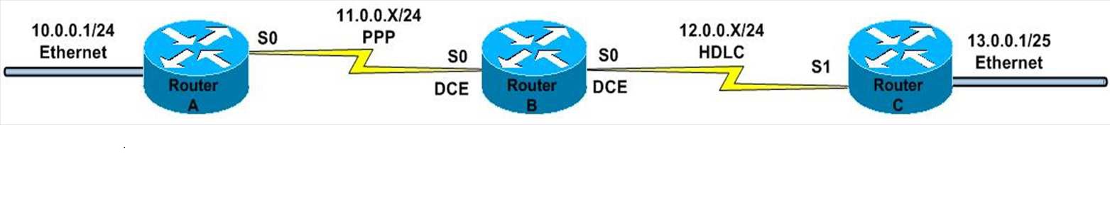
Example: Let us consider a simple network running RIP version 2
(as shown figure). The network numbers are 10.0.0.0, 11.0.0.0, 12.0.0.0, and
13.0.0.0. We know that each router should be able to see all of the networks.
For Router A, we know that networks 10.0.0.0 and 11.0.0.0 are directly
connected to the router. Networks 12.0.0.0, and 13.0.0.0 should be in the
routing table as a RIP route. In order for this to happen all of the interfaces
connected to the other routers should be up/up and the correct routes should be
in the routing table Rather than checking to see if the cables are attached
first check to see if the router can see the other networks
RouterA# show ip route | begin Gateway
Gateway of last resort is not set
C 10.0.0.0/24 is directly connected, 10.0.0.1 We can see that
only the directly connected Ethernet network can be seen. The WAN network is
not there. Start at
layer 1 and check that the router can see the cable
RouterA# show controllers serial 0
HD unit 0, idb = 0x1AE828, driver structure at 0x1B4BA0
buffer size 1524 HD unit 0, V.35 DTE cable
So we can see that the cable is attached. It is a DTE cable, so
we know we do not need to use the “clock rate” command on this interface. If
the cable on the other end was DCE then it should have the “clock rate” command
configured on it. Next we need to check layer 2. The interface has a cable
attached but is it showing up/up?
RouterA#show ip interface brief
Interface IP-Address OK? Method Status Protocol
Serial0 11.0.0.1 YES unset administratively down down
Ethernet0 10.0.0.1 YES unset up up
Troubleshooting
Somebody has neglected to open or “no shutdown” the serial
interface. This can easily be corrected with the “no shut” command
RouterA#config terminal
RouterA(config)#interface serial 0
RouterA(config-if)#no shutdown
%LINK-3-UPDOWN: Interface Serial0, changed state to up
RouterA(config-if)#end
%LINK-3-UPDOWN: Interface Serial0, changed state to down
%LINEPROTO-5-UPDOWN: Line protocol on Interface Serial0, changed
state to down
We should now look at the interfaces to see if there is a
difference
RouterA#show ip interface brief
Interface IP-Address OK? Method Status Protocol
Serial0 11.0.0.1 YES unset up down
Ethernet0 10.0.0.1 YES unset up up
Okay, so now the interface is administratively up; however, it
is showing as up/down. If the serial interface cannot see keepalives from the
other interface then it will remain up/ down. We need to examine the
configuration on our serial interface and compare it with its neighbor on
Router B
RouterA#show run interface serial 0
interface Serial0
ip address 11.0.0.1 255.255.255.0
no ip directed-broadcast
encapsulation ppp
The encapsulation type is set to PPP that is not the default
HDLC. The diagram indicates that this side should be using PPP. On Router B, we
would also check to make sure the interfaces are up/up We can see that the
interface connected to Router A is down down. We can check the configuration on
the interface to see what could be wrong
RouterB#show run interface serial 0
interface Serial0
ip address 11.0.0.2 255.255.255.0
no ip directed-broadcast
clock rate 128000 « clock rate present
We can immediately see a difference between the configurations
on Router A and Router B. Router A's serial interface shows that the
encapsulation is set to PPP. Router B does not show an encapsulation type
because it is left at the default for Cisco which is HDLC
RouterB#show interface serial 0
Serial1 is down, line protocol is down
Hardware is HD64570
Internet address is 12.0.0.1/24
MTU 1500 bytes, BW 1544 Kbit, DLY 1000 usec, rely 255/255, load
1/255
Encapsulation HDLC, loopback not set, keepalive set (10 sec)
RouterB#show ip interface brief
Interface IP-Address OK? Method Status Protocol
Serial0 11.0.0.2 YES unset up Down
Serial1 12.0.0.1 YES unset down Down
Ethernet0 unassigned YES unset administratively down Down
Ethernet1 unassigned YES unset administratively down Down
Bri0 unassigned YES unset administratively down Down
Bri0:1 unassigned YES unset administratively down Down
Bri0:2 unassigned YES unset administratively down Down
Troubleshooting
We can now change the encapsulation type (layer 2) to HDLC
RouterA#config t
RouterA(config)#interface serial 0
RouterA(config-if)#encapsulation hdlc
RouterA(config-if)#end
%LINK-3-UPDOWN: Interface Serial0, changed state to up
%LINEPROTO-5-UPDOWN: Line protocol on Interface Serial0, changed
state to up
%SYS-5-CONFIG_I: Configured from console by console
So now we are satisfied that layers 1 and 2 are now operational.
To confirm, we ping Router A from Router B
RouterA#ping 11.0.0.2
Type escape sequence to abort.
Sending 5, 100-byte ICMP Echos to 11.0.0.2, timeout is 2
seconds:
!!!!!
Success rate is 100 percent (5/5), round-trip min/avg/max =
1/2/4 ms
We can now check the routing table for Router A to see if it can
see the rest of the network
RouterA#show ip route | begin Gateway
Gateway of last resort is not set
C 10.0.0.0/24 is directly connected, 10.0.0.1
C 11.0.0.0/24 is directly connected, 11.0.0.1
R 12.0.0.0/24 [120/1] via 11.0.0.2, 00:01:33, Serial0
This is better than before; however, we still can only see as
far as network 12.0.0.0. We could check on Router B, but since network 13.0.0.0
is connected to Router C, we can start there
Both interfaces are up/up, so we know that the Ethernet
interface can see its own network (13.0.0.0) and that the serial interface is
capable of advertising the route. Layers 1 and 2 appear fine, so we can check
layer 3. We could type in the “show run” command; however, we could be more
specific than that
RouterC#show ip protocols
Routing Protocol is "rip"
Sending updates every 30 seconds, next due in 19 seconds
Invalid after 180 seconds, hold down 180, flushed after 240
Outgoing update filter list for all interfaces is not set
Incoming update filter list for all interfaces is not set
Redistributing: rip
Default version control: send version 2, receive version 2
Interface Send Recv Triggered RIP Key-chain
Ethernet0 2 2
Serial0 2 2
Automatic network summarization is not in effect
Maximum path: 4
Routing for Networks:
12.0.0.0
14.0.0.0
Routing Information Sources:
Gateway Distance Last Update
12.0.0.1 120 00:00:17
Distance: (default is 120)
RouterB#show ip interface brief
Interface IP-Address OK? Method Status Protocol
Serial0 11.0.0.1 YES unset up Up
Ethernet0 10.0.0.1 YES unset up Up
RouterC#show ip interface brief
Interface IP-Address OK? Method Status Protocol
Serial0 12.0.0.2 YES unset up Up
Ethernet0 13.0.0.1 YES unset up Up
Troubleshooting
The problem appears to be that although network 13.0.0.0 is
attached to ethernet 0, the router has been configured to advertise network
14.0.0.0.We can easily correct this problem
RouterC#configure terminal
RouterC(config)#router rip
RouterC(config)#version 2
RouterC(config-router)#no network 14.0.0.0
RouterC(config-router)#network 13.0.0.0
RouterC(config-router)#^Z
%SYS-5-CONFIG_I: Configured from console by console
RouterC#show ip protocols
Routing Protocol is "rip"
Sending updates every 30 seconds, next due in 19 seconds
Invalid after 180 seconds, hold down 180, flushed after 240
Outgoing update filter list for all interfaces is not set
Incoming update filter list for all interfaces is not set
Redistributing: rip
Default version control: send version 2, receive version 2
Interface Send Recv Triggered RIP Key-chain
Ethernet0 2 2
Serial0 2 2
Automatic network summarization is in effect
Maximumpath: 4
Routing for Networks:
12.0.0.0
13.0.0.0
Routing Information Sources:
Gateway Distance Last Update
12.0.0.1 120 00:00:17
Distance: (default is 120)
We are now advertising the correct networks. We should check
that Router C can see all of the networks before we move on
RouterC#show ip route
Codes: C - connected, S - static, I - IGRP, R - RIP, M - mobile,
B - BGP
D - EIGRP, EX - EIGRP external, O - OSPF, IA - OSPF inter area
E1 - OSPF external type 1, E2 - OSPF external type 2, E - EGP
i - IS-IS, L1 - IS-IS level-1, L2 - IS-IS level-2, * - candidate
default
U - per-user static route
Gateway of last resort is not set
C 12.0.0.0/24 is directly connected, 12.0.0.2
C 13.0.0.0/24 is directly connected, 13.0.0.1
R 11.0.0.0/24 [120/1] via 12.0.0.1, 00:07:13, Serial0
R 10.0.0.0/24 [120/2] via 12.0.0.1, 00:06:37, Serial0
We can go back to Router A to see if it can see all of the
networks
RouterA#show ip route
Codes: C - connected, S - static, I - IGRP, R - RIP, M - mobile,
B - BGP
D - EIGRP, EX - EIGRP external, O - OSPF, IA - OSPF inter area
E1 - OSPF external type 1, E2 - OSPF external type 2, E - EGP
i - IS-IS, L1 - IS-IS level-1, L2 - IS-IS level-2, * - candidate
default
U - per-user static route
Gateway of last resort is not set
C 10.0.0.0/24 is directly connected, 10.0.0.1
C 11.0.0.0/24 is directly connected, 11.0.0.1
R 12.0.0.0/24 [120/1] via 11.0.0.2, 00:04:17, Serial0
R 13.0.0.0/24 [120/2] via 11.0.0.2, 00:04:34, Serial0
All the routes are now visible
CCNA: OSPF CHEAT SHEET
Key Characteristics
Type: Link State
Algorithm: Dijkstra’s (Shortest Path First) Algorithm
Standard: RFC 2328
Administrative Distance: 110
Metric: Cost
Protocol/Protocol Number: IP/89
Authentication: Yes (MD5 and Plain Text)
Supports VLSM and Route Summarization
Support for IPv6 (RFC 2740)
Fast Convergence
Metric Calculation
Cost = 100 Mbps / Link Speed
OSPF cost can be modified in three ways:
1. (config-if)#ip ospf cost
2. (config-if)#bandwidth
3. (config-router)#auto-costreference-bandwidth
Neighbor Process
To become neighbors OSPF routers must be agree on the
following parameters
1. Area ID
2. Same subnet
3. Authentication (if used)
4. Hello Interval and Dead Interval
5. Area Type (Stub, NSSA)
6. Router IDs must be unique
OSPF Neighbor States
Down: Previously known neighbor has failed
Init: an interim state in which Hello has been heard from the
neighbor but that Hello does not list the local router’s RID
Two-way: the neighbor has sent a Hello that lists the local
router’s RID in the list of seen routers
Full: Both routers complete the database exchange process and
have identical LSDB. Fully adjacent Router ID (RID) Router ID must be
configured before an OSPF process
could be started.
Cisco Routers uses the following criteria to select arouter ID:
1. RID configured with “router-id” command
2. If manual RID not configured, select the highest number IP
address on any loopback interface in “up/up” state
3. If loopback interfaces not configured, select the highest
number IP address on any non-loopback interface in “up/up” state
Router Types
Internal Router: whose (all) interfaces resides within the same
area
Backbone Router: A router that resides in the backbone area
Area Border Router: an ABR connect two or more Areas
ASBR: Autonomous System Boundary Router or an ASBR connects an
external routing domain to an OSPF routing domain
Route Types and Preference
Intra-Area Routes: A route to a network in the same area as the
router. Denoted by “O” in the routing table.
Inter-Area Routes: A route to a network in another area as the
router. Denoted by “O IA” in the routing table
External Route: A route to network that is external to the OSPF
routing domain. Denoted by ‘E1’ or ‘E2’ in the routing table.
Routes Preference:
1. Intra-Area (O) > Inter-Area (O IA)
2. Inter-Area (O IA) > External Type-1 (E1)
3. External Type-1 (E1) > External Type-2 (E2)
Areas
OSPF runs SPF algorithm and requires a lot of processing power
and memory. If the size of network is too large this could cause slower
convergence and can lead to following problems:
1. more memory is required to maintain the link state database
2. more processing power is required to process the link state
database
3. the links state database grows exponentially with the size of
OSPF domain
4. a single change in network topology (for example: link
up/down) would trigger all routers to re-run the SPF (again) to calculate the
shortest path
To cope with these problems, areas are configured. There are two
basic types:
1. Backbone Area or Area 0: All other area must be connected to
area 0
2. Non-backbone Area: any other area with area-id other than
zero
Timers
Hellos are sent to multicast address: 224.0.0.5 (ALLSPFRouters)
Broadcast Multi-access and p2p= 10 seconds
NBMA = 30 seconds
Dead Timer = Four Times the hello interval
Broadcast and p2p= 40 seconds
NBMA = 120 seconds
To change hello and dead intervals use the command ‘config-if)#
ip ospf hello-interval seconds’ and ‘config-if)# ip ospf dead-interval seconds’
Designated Router (DR) / Backup DR (BDR) Election
There are two problems with multi-access networks:
1. For “N” routers, it requires “N(N-1)/2” adjacencies
2. Flooding of this excess LSAs would be chaotic itself for the
network
DR/BDR addresses the challenge of adjacency creation and LSA
flooding on multi-access networks only
No election on P2P and P2MP network type
The following criteria is used for DR/BDR election:
1. Router with highest interface priority is elected as DR
2. Any other router with second highest priority is elected as
BDR
3. If priority is equal, highest RID is used as tie-breaker
4. The DR/BDR election is held between two or more neighbors who
reach the TWO-WAY state
The priority ranges from 0-to-255 and default value is 1
Priority of 0 means that router will not take part in DR and BDR
election
DR is never preempted even if a router with better priority is
present. Manual reset is required for preemption If a router becomes active and
it checks for an active DR and BDR on the network. If there already is an
active DR and BDR on the segment, the new router simply accepts them. If there
is not, then an election is held for DR/BDR selection After the DR/BDR have
been elected, the other router known as DROthers establish adjacencies with DR
and BDR only Neighbors are still tracked on multicast address: 224.0.0.5 but
DROthers multicast updates to AllDRRouters address: 224.0.0.6. Only DR and BDR
listen to this address and DR in-turn flood updates to DROthers on 224.0.0.5
DR/BDR is property of a router’s interface not the router itself
Virtual Links
It is link through non-backbone area to backbone area.
Used to connect:
1. an area to backbone area through non-backbone area
2. a partitioned backbone area through non-backbone area
Rules:
1. A virtual link can only be configured between ABRs
2. The transit area must have full routing information and it
cannot be stub
Single Area

Router R1:
interface loopback 0
ip address 10.1.1.1 255.255.255.255
!
interface serial 0/0
ip address 192.168.12.1 255.255.255.0
!
router ospf 100
router-id 1.1.1.1
network 192.168.12.0 0.0.0.255 area 0
network 10.1.1.1 0.0.0.0 area 0
Router R2:
interface loopback 0
ip address 10.2.2.2 255.255.255.255
!
interface serial 0/0
ip address 192.168.12.2 255.255.255.0
!
router ospf 100
router-id 2.2.2.2
network 192.168.12.0 0.0.0.255 area 0
network 10.2.2.2 0.0.0.0 area 0
• Configuration Example
R2# show ip route | begin Gateway
Gateway of last resort is not set
C 192.168.12.0/24 is directly connected, Serial0/0
10.0.0.0/8 is variably subnetted, 2 subnets, 2 masks
C 10.2.2.0/24 is directly connected, Loopback0
O 10.1.1.1/32 [110/65] via 192.168.12.1, 00:00:02, Serial0/0
Multi-Area

Router R1:
interface loopback 0
ip address 10.1.1.1 255.255.255.255
!
interface serial 0/0
ip address 192.168.12.1 255.255.255.0
!
interface serial 0/1
ip address 192.168.13.1 255.255.255.0
!
router ospf 100
router-id 1.1.1.1
network 192.168.12.1 0.0.0.0 area 0
network 192.168.13.1 0.0.0.0 area 1
network 10.1.1.1 0.0.0.0 area 0
Router R2:
interface loopback 0
ip address 10.2.2.2 255.255.255.255
!
interface serial 0/0
ip address 192.168.12.2 255.255.255.0
!
router ospf 100
router-id 2.2.2.2
network 192.168.12.2 0.0.0.0 area 0
network 10.2.2.2 0.0.0.0 area 0
Router R3:
interface serial 0/0
ip address 192.168.13.3 255.255.255.0
!
interface loopback 0
ip address 10.3.3.3 255.255.255.255
!
router ospf 100
router-id 3.3.3.3
network 192.168.13.3 0.0.0.0 area 1
network 10.1.1.3 0.0.0.0 area 1
R2# show ip route | begin Gateway
Gateway of last resort is not set
C 192.168.12.0/24 is directly connected, Serial0/0
O IA 192.168.13.0/24 [110/128] via 192.168.12.1, 00:00:03,
Serial0/0
10.0.0.0/8 is variably subnetted, 3 subnets, 2 masks
O IA 10.3.3.3/32 [110/129] via 192.168.12.1, 00:00:12, Serial0/0
C 10.2.2.0/24 is directly connected, Loopback0
O 10.1.1.1/32 [110/65] via 192.168.12.1, 00:00:12, Serial0/0
OSPF Troubleshooting Command
1. show ip protocols
2. show ip ospf []
3. show ip route [ospf]
4. show ip ospf interface [brief | ]
5. show ip ospf neighbor
6. show ip ospf database
7. debug ip ospf [hello | adjacency | events]
No comments:
Post a Comment
Note: only a member of this blog may post a comment.