1.There is a
series of 2^n say 2,4,8 so on .. Given a number say Y how do you find you whether
it belongs to the series or not?
Or Find whether
a number is power of two of not. Give the Logic here.
Sample Example:
Input : n = 4
Output : Yes
22 = 4
Input : n = 7
Output : No
Input : n = 32
Output : Yes
25 = 32
Solution 1:
Solution is to keep dividing
the number by two, i.e, do n = n/2 iteratively. In any iteration, if n%2
becomes non-zero and n is not 1 then n is not a power of 2. If n becomes 1 then
it is a power of 2.
Solution 2:
All power of two numbers have
only one bit set. So count the no. of set bits and if you get 1 then number is
a power of 2
| Power of Two | 32-Bit Unsigned Integer Representation |
|---|---|
| 20 | 00000000000000000000000000000001 |
| 21 | 00000000000000000000000000000010 |
| 22 | 00000000000000000000000000000100 |
| … | … |
| 229 | 00100000000000000000000000000000 |
| 230 | 01000000000000000000000000000000 |
| 231 | 10000000000000000000000000000000 |
For More Solutions refer to
the following link.
2.
List a
directory in linux ls -d */
List recursively directory tree
How to make 100 directory in linux using one command.
mkdir {A..Z}
mkdir {1..100}
How to check if interface is up or not in linux.
--$ ethtool eth0
How to make 100 directory in linux using one command.
mkdir {A..Z}
mkdir {1..100}
How to check if interface is up or not in linux.
--$ ethtool eth0
Settings for
eth0:
Supported ports: [ TP ]
Supported link modes: 10baseT/Half 10baseT/Full
100baseT/Half
100baseT/Full
1000baseT/Full
Supports auto-negotiation: Yes
Advertised link modes: 10baseT/Half 10baseT/Full
100baseT/Half
100baseT/Full
1000baseT/Full
Advertised pause frame use: No
Advertised auto-negotiation: Yes
Speed: 1000Mb/s
Duplex: Full
Port: Twisted Pair
PHYAD: 1
Transceiver: internal
Auto-negotiation: on
MDI-X: on
Supports Wake-on: pumbg
Wake-on: g
Current message level: 0x00000001 (1)
Link detected: yes
3. What is
difference between L3 Switch and Router.
- L3
Switch do switching at layer 3 by preserving the source and destination mac and
preserving the TTL value of the IP header of the 1st routed packet, so the first packet is routed using normal routing lookup, but after that all packet are switched.
- router do
normal routing lookup, but by introducing fast switching and CEF, packets are
also now switched on a router.
- Switches
doesnt support some QoS features.
- Switches
doesnt support NAT.
- The
forwarding on switches is done on ASIC (Application Specific Integrated
Circuits) which is done in hardware rather than a software.
-
Forwarding on routers are done in a software.
- router
supports different WAN technologies (modules) unlike switches.
- L2 switch is mac address based whereas L3
switch is based on logical address.
- Creating vlans in L2 switch and communicating
between vlans is not possible. Communication between vlans is possible in L3
Switch.
-With L3 switch we can connect to WAN link but
it is not possible with L2 switch.
4.How
switch operates? Concept on port based, mac address and normal mac address? How
unicast and broad cast happens in these cases?
An Ethernet switch is mainly used to forward
packets at the data link layer, that is, transmit the packets to the
corresponding ports according to the destination MAC address of the packets. To
forward packets quickly, a switch maintains a MAC address table, which is a
Layer 2 address table recording the MAC address-to-forwarding port association.
Each entry in a MAC address table contains the following fields:
Destination MAC address
ID of the VLAN which a port belongs to
Forwarding egress port numbers on the local switch
When forwarding a packet, an Ethernet switch
adopts one of the two forwarding methods based upon the MAC address table
entries.
Unicast forwarding: If the destination MAC address
carried in the packet is included in a MAC address table entry, the switch
forwards the packet through the forwarding egress port in the entry.
Broadcast forwarding: If the destination MAC
address carried in the packet is not included in the MAC address table, the
switch broadcasts the packet to all ports except the one receiving the packet.
Each hardware device that you connect to your
Ethernet network has a unique MAC address assigned to it by the device’s
manufacturer. For example, every network interface card (NIC) that you use to
connect your computers to your network has a MAC address assigned to it by the
adapter’s manufacturer.
The switch contains a MAC address table with a
storage capacity of up to 16,000 entries. The switch uses the table to store
the MAC addresses of the network nodes connected to its ports, along with the
port number on which each address was learned.
The switch learns the MAC addresses of the end
nodes by examining the source address of each packet received on a port. It
adds the address and port on which the packet was received to the MAC table if
the address has not already been entered in the table. The result is a table
that contains all the MAC addresses of the devices that are connected to the
switch’s ports, and the port number where each address was learned.
When the switch receives a packet, it also
examines the destination address and, by referring to its MAC address table,
determines the port where the destination node is connected. It then forwards
the packet to the appropriate port and on to the end node. This increases
network bandwidth by limiting each frame to the appropriate port when the
intended end node is located, freeing the other switch ports for receiving and
transmitting data.
If the switch receives a packet with a destination
address that is not in the MAC address table, it floods the packet to all the
ports on the switch. If the ports have been grouped into virtual LANs, the
switch floods the packet only to those ports which belong to the same VLAN as
the port on which the packet was received. This prevents packets from being
forwarded onto inappropriate LAN segments and increases network security. When
the destination node responds, the switch adds its MAC address and port number
to the table.
If the switch receives a packet with a destination
address that is on the same port on which the packet was received, it discards
the packet without forwarding it on to any port. Because both the source node
and the destination node for the packet are located on the same port on the
switch, there is no reason for the switch to forward the packet. This too
increases network performance by preventing frames from being forwarded
unnecessarily to other network devices.
The type of MAC address described above is
referred to as a dynamic MAC address. Dynamic MAC addresses are addresses that
the switch learns by examining the source MAC addresses of the frames received
on the ports.
Dynamic MAC addresses are not stored indefinitely
in the MAC address table. The switch deletes a dynamic MAC address from the
table if it does not receive any frames from the node after a specified period
of time. The switch assumes that the node with that MAC address is no longer
active and that its MAC address can be purged from the table. This prevents the
MAC address table from becoming filled with addresses of nodes that are no
longer active.
The period of time that the switch waits before
purging an inactive dynamic MAC address is called the age-out time. The default
value is 300 seconds (5 minutes) and the range is 15 to 3000 seconds.
5. If
switch is connected to four ports. Then how many mac address will be there in
switch ?
For every port, there will be one mac address.
Apart from this switch has one default mac address ie for vlan 1 used for
management purpose(used in case of managed switch).
6. What
happens when hub is connected in between of two switches . what will happen
when one of the links connected to hub goes down . how stp work?
Hub won’t have any effect in topology since hub is
L1 device.
7. Why is
a MAC address not a true address?
An address specifies a location. A MAC address is
not a true address because it is permanently associated with the interface of a
specific device and moves whenever the device moves. A MAC identifies the
device, not the location of the device.
8. What
happens when one computer (C1) wants to communicate with another computer (C2)
in a LAN segment?
When it comes to the Layer 2 communications
between networked systems, IP address is not used. So, within a LAN segment
computers identify each other and communicate with each other using the MAC Address.
So, when Computer (C1) gets the target IP address of the Computer (C2) it wants
to communicate with,
It first looks at its own ARP cache (which is a
table that contains the IP addresses and their corresponding MAC addresses for
computers/ systems within a network) to see if it already has the MAC address
for the computer (C2), it wants to communicate with.
If the MAC address of C2 is present in its ARP
cache table, it can then append the message with the corresponding MAC address
and send it over the network (cable, switch).
If the MAC address of C2 is not present in its ARP
cache table, C1 will broadcast an ARP request message to all the computers /
systems in the network indicating that it wants the MAC address for the IP
address in its possession.
This ARP request is received by all the systems in
the network, but only the computer with the target IP address (C2) responds to
C1 with an ARP reply message, indicating its MAC address.
Now since C1 has both IP address and MAC address
of C2, it will communicate with C2 using this information. In the process, both
C1 and C2 update their ARP cache tables with the newly acquired information so
that the next time the ARP broadcast message can be avoided.
9. What
is an ARP Cache / Cache Table?
Since computers cannot send broadcast messages
every time they need to connect with another network device, they store the IP
addresses and the corresponding MAC addresses of systems they frequently
communicate with, in a table called ARP Cache table. All the systems in the LAN
maintain this table. The entries in the ARP cache table are generally short
lived and are updated every 15-20 minutes.
Since a LAN segment consists of a number of
computing devices, some individual ARP table entries are removed if the system
doesn’t communicate with certain devices for considerable amount of time. This
is done mainly to limit the size of ARP cache.
10. What
is ARP Poisoning?
The Address Resolution Protocol itself doesn’t
come with any authentication / protection mechanism. So, ARP requests or/and
replies can be forged by malicious systems under the control of hackers. If a
forged ARP request/ reply is used to update the ARP cache of another system,
the process is called ARP poisoning. This is mainly done to redirect network
traffic for malicious purposes.
11. What
is ARP broadcast storm?
The ARP traffic on a network can be around 10% of
the network traffic during normal times and up to 85% of the network traffic
during abnormal network conditions caused by ARP broadcast storm. Basically,
ARP requests are broadcast multiple times or to multiple systems (sometimes
more than thousand requests within a second) during an ARP broadcast storm
thereby taking up a lot of network bandwidth and thereby making normal network communications
difficult.
This can happen due to a lot of reasons and some
of them are given below:
ARP request for a non existent host triggers a
series of ARP messages within a short interval of time. Its only eventually
that ARP gives up.
Virus/ malware in
a system can generate a lot of ARP broadcast messages in order to create a DOS
type of network attack.
If there are loops within the network that are not
prevented by using protocols like STP/ RSTP, ARP requests would be looped back
and fourth between switches creating an ARP broadcast storm.
Incorrect router configuration, Network Interface
Card/ Network Switch malfunction can also create ARP broadcast storms.
A large unsegmented network is especially
susceptible to excessive ARP broadcasts/ broadcast storms and hence it is
always a good practice to sub-divide a large network into various segments
(using VLAN’s etc) and enable Inter-VLAN routing using Layer-3 switches. This
limits the broadcast domain to a limited number of systems.
So, next time when there is a congestion in the
network, you can monitor for ARP broadcast storms as well. You can use network
monitoring tools like Wireshark to monitor for abnormal ARP activity.
12. What is
default route?
Also known as the gateway of last resort, a
default route is a special type of static route with an all-zeros network and
network mask. The default route is used to route any packets to a network that
a router does not directly know about to a next-hop router. By default, if a
router receives a packet to a destination network that is not in its routing
table, it drops the packet. When a default route is specified, the router does
not drop the packet. Instead, it forwards the packet to the IP address
specified in the default route.
13. What is an IP Helper address feature and why is
it required in a DHCP environment
DHCP Discover packets are broadcast packets.
This means that a DHCP Discover packet which is sent from the client would not
reach the DHCP Server , if the server resides on a different network. This is
because, routers are required for communication between different networks and
routers do not forward broadcast packets. The IP Helper address feature is
configured on the router. The feature informs the router the DHCP Servers IP
address for the network. So, when the router receives the DHCP Discover packet,
it would convert it from broadcast to unicast packet and then send it to the
DHCP Server.
15. What
are benefits of routing?
Broadcast control
Multicast control
Optimal path determination
Traffic management
Logical addressing
Layer 3 security
16. Benefits
of L3 Switching?
Hardware-based packet forwarding
High-performance
packet switching
packet switching
High-speed
scalability
scalability
Low latency
Lower per-port cost
Flow accounting
Security
QoS
Layer 3 switching is hardware-based routing. A
full Layer 3 switch does everything to a packet that a traditional router does.
Layer 3 switching is a combination of Layer 2
switching and Layer 3 routing to that provides integrated switching and
routing.
While a router is like a mailroom with a single
chute, a switch provides multiple chutes to direct data. Traditionally,
applications at Layer 2 are responsible for the validity and integrity of
transmission from node to node. However, the advent of the Internet has meant
that most network traffic is now on a backbone system. Smart switches are now
able to do most of the functions of a router.
Layer 3 switches can be used to prioritize traffic
and can control larger networks than Layer 2 switches, reducing the need to
create subnets isolated by routers.
The primary difference between the
packet-switching operation of a router and a Layer 3 switch is the physical
implementation. In general-purpose routers, microprocessor-based engines
typically perform packet switching. A Layer 3 switch performs packet switching
with hardware.
Layer 3 devices can interrogate packets to
determine priorities to allocate bandwidth, and this is where Quality of
Service (QoS) features are usually implemented.
When performing Layer 3 functions, a switch reads
the TCP and User Datagram Protocol (UDP) fields to determine what type of
information the packet is carrying. The network manager can then program the
switch to prioritize traffic by application.
When being used for QoS purposes, this means that
a videoconferencing application might be granted more bandwidth than an e-mail
message.
If the network is only at 50 percent capacity on
the backbone, each user or application on the network is already getting the
same QoS without Layer 4 switching.
18.What is
auto-negotiation?
The Auto-Negotiation function is an optional part
of the Ethernet standard that makes it possible for devices to exchange
information about their abilities over a link segment. This, in turn, allows
the devices to perform automatic configuration to achieve the best possible
mode of operation over a link.
At a minimum, Auto-Negotiation can provide
automatic speed matching for multi-speed devices at each end of a link
Multi-speed Ethernet interfaces can then take advantage of the highest speed
offered by a multi-speed hub port.
Stress: Auto-negotiation is not a fully
implemented standard and, therefore, the behavior of the link cannot be
guaranteed when using this feature.
Cisco strongly recommends that each end of the
link be manually configured for the desired duplex and speed.
19. What is
ping used for?
The ping command sends a specified number of ICMP
echo requests and measures the time the destination device takes to respond to
each request
To test connectivity to remote hosts.
Switch (enable) ping destination ip address
The ping command will return one of the following
responses:
Success rate is 100 percent or ip address is
alive. This response occurs in 1 to 10 seconds, depending on network traffic
and the number of ICMP packets sent.
Destination does not respond. No answer message is
returned if the host does not respond.
Unknown host. This response occurs if the targeted
host does not exist.
Destination unreachable. This response occurs if
the default gateway cannot reach the specified network
Network or host unreachable. This response occurs
if there is no entry in the route table for the host or network.
20. List
the five Spanning-Tree Protocol port states and describe their function.
The five Spanning Tree states are Blocked, Listen,
Learn, Forward, and Disabled.
Blocked is the initial state of the port. A port will also be placed in a blocked state
if there is a redundant path to the Root Bridge and the port does not have the
best cost. Blocked means that the port can
send and receive BPDUs but cannot send or receive data.
21. Identify at least one network problem caused by Spanning-Tree Protocol.
Following are three network problems caused by
Spanning Tree
-- Convergence time after a network failure.
-- The time that it takes a port to move into
forwarding mode will cause many workstations to time out while attempting to
attach to a service.
-- Paths can be sub-optimal if network is not
designed correctly
22.
Explain the solutions developed to improve STP convergence time.
Spanning-Tree Protocol operation.
The following solutions improve spanning tree
PortFast – enables a port to bypass Spanning Tree
operations
UplinkFast – creates an UplinkFast group of ports
that can be used to perform a rapid failover in the case of a direct link
failure.
BackboneFast – expires the Max Age timer when it
stops hearing the superior BPDU but continues hearing the inferior BPDU
EtherChannel – bundles parallel ports together
which allows Spanning Tree to treat them as one port
Root Bridge – correct placement of the Root Bridge
and modification of the diameter will improve path selection and convergence
time.
Port Priority and Port Cost – Used to influence
the path selections made by Spanning Tree
23. How to
perform inter vlan routing without layer 3 device?
Yes this is possible by configuring link between
the two switches as access ports.
24. What
is the purpose of the TTL field in the IP header? How does the TTL process
work?
The Time to Live (TTL) field prevents
"lost" packets from being passed endlessly through the IP
internetwork. The field contains an 8-bit integer that is set by the originator
of the packet. Each router through which the packet passes will decrement the
integer by one. If a router decrements the TTL to zero, it will discard the
packet and send an ICMP "time exceeded" error message to the packet's
source address.
25. What
is the difference between the ip default−gateway, ip default−network, and ip
route 0.0.0.0/0 commands?
The ip default−gateway command is used when IP routing
is disabled on the router. However, ip default−network and ip route 0.0.0.0/0
are effective when IP routing is enabled on the router and they are used to
route any packets which do not have an exact route match in the routing table
26. What
is the difference between the two methods to create static routes?
There are two methods to create static routes:
The ip route 10.1.1.1 255.255.255.0 eth 0/0 command
generates an ARP broadcast that looks for the next−hop IP address.
The ip route 10.1.1.1 255.255.255.0 172.16.1.1 command
does not generate an ARP request. It keeps Layer 2 out of the routing process.
27. What
is difference between distance vector and link state protocols?

28. Are
Vlan locally significant?
One common misconception regarding VLANs is that
they are significant beyond a single switch. Of course, VLAN numbers have to
match for trunking to work, and VTP can be used to automatically propagate VLAN
information. However, a VLAN, being essentially little more than a number, is
significant only within a device. Consider the following scenario:

All of the ports on switch A are set to access mode
in VLAN 10, and all of the ports on switch B are set to access mode in VLAN 20.
Note that the connection between the two switches is not a trunk; each end is
configured as an access port in the respective VLAN. Our two hosts A and B are
similarly connected to different VLANs, but still reside in the same IP subnet.
Can hosts A and B communicate?
The answer is yes. Follow the path of a frame
leaving host A destined for host B. Switch A receives this frame on a port in
VLAN 10, so it can only egress out another port in VLAN 10 or a trunk port. It
performs the usual MAC lookup to determine the appropriate outbound port is its
link to switch B. Now, here's the key: the frame is forwarded to switch B
without a VLAN tag, because this is an access port. Switch B receives the frame
on an interface it considers VLAN 20 and performs the same switching decision
to forward the frame to host B.
So, does it work? Yep! Is it a good idea? Probably
not. In an instance where VLANs are used, you're probably using more than one.
For this reason and others, it's recommended to always trunk between switches
using IEEE 802.1q or (less favorably) Cisco ISL.
29. How to
create host route in Linux?
To add a static host route on Linux, run:
route add -host <destination IP address> gw
<gateway IP address>
or
route add <destination IP address> gw
<gateway IP address>
Example:
Security gateway's external IP address is
192.168.1.1
Security gateway's internal IP address is 10.1.1.1
The desired Static NAT IP address is 192.168.1.20
The internal host to be translated is 10.1.1.20
Use the following command:
route add -host 192.168.1.20 gw 10.1.1.20
or
route add 192.168.1.20 gw 10.1.1.20
Alternately,
the static routes can be entered in the /etc/sysconfig/static-routes
file in this format:
eth1 net 192.168.1.20 netmask 255.255.255.255 gw
10.1.1.20
where eth1 is the gateway's internal interface.
The /etc/sysconfig/static-routes file will be
parsed by Linux kernel at startup.
To verify that route was added successfully, check
the routing table by running netstat –rn
30. Collision
and broadcast domain difference
A switch has 4 ports. Now 2 ports are assigned to
vlan 1 and next 2 ports are assigned to vlan 2 . How many collision domains will
be there?
Collision domain should remain same.
31. How to
create sub interfaces in Linux or host?
Create sub interfaces on CentOS and Redhat
Sub interfaces or virtual interfaces are used for
a number of reasons. Normally for VLANs, but also if you want your machine to
have multiple IP addresses.
This is relatively straight forward to do.
It can be done from the command line like this:
# ifconfig eth0:1 192.168.111.1
The above command has just created a virtual / sub
interface on eth0 called eth0:1 and assigned it the IP 192.168.111.1
This however is not a permanent solution because
when you reboot, this interface will be lost. To make it permanent we need to
create a file in /etc/sysconfig/network-scripts/ called ifcfg-eth0:1
DEVICE=eth0:1
BOOTPROTO=none
HWADDR=00:16:17:90:a5:15
ONPARENT=yes
IPADDR=192.168.111.1
NETMASK=255.255.255.0
TYPE=Ethernet
Very similar to ifcfg-eth0 but note there is no
default gateway set. Always remove the gateway line from the cfg file you will
inevitably copy to create this.
The MAC or Hardware address must also match the
parent interface.
If you need more than one virtual / sub interface,
simply create more config files.
To bring an interface up after creating the config
file use:
# ifup eth0:1
32. Define Bandwidth and Latency?
- Bandwidth/ Throughput – It means the number of
bits which can be transmitted over the network in a specified time.
- Latency – It is the time taken by a message to
travel from one side to another.
Bandwidth
and latency describe the performance of a network.
33. Where
exactly vlan tag is placed in Ethernet header?

34. what is difference between LAG and LACP?
LAG : Link
aggregation group(LAG) – combination of multiple links between two devices to
form a single(larger ) link
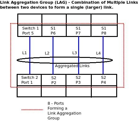
LAG is a process of inter-connecting two switches
with two or more links between them (or between a switch and a server), so that
multiple links are combined into one bigger virtual link that can carry a
higher (combined) bandwidth. All these multiple links participating in a Link
Aggregation Group act like a single large (virtual) link.
LAG is also used for increasing link reliability.
Since multiple links connect two devices, even if one fails the other links
keep carrying the information and the traffic on the failed link is also
transferred to them. That way, loss of a single link between two switches
doesn’t stop the communication between them. Multiple links participating in a
LAG can also load-balance the traffic between them so that traffic is evenly
distributed.
The number of links that can combine to form a
larger link between two devices is generally restricted by the hardware vendor.
LAG is a static protocol and needs to be configured individually for each pair
of physical ports. LAG is a standard.
LACP – Link
Aggregation Control Protocol
LACP is similar to LAG, where multiple ports/links
between two switches combine to provide higher bandwidth links between them.
Additionally, ports that are LACP enabled can automatically configure
themselves into trunk groups, without any manual configuration/intervention.
The main purpose of LACP is to automatically
add/delete individual links to the aggregate bundle, while adding new links and
also after recovering from link failures. LACP can monitor to verify if all the
links are connected to the right group. Basically, LACP helps automate the
configuration and maintenance of LAG’s.
LACP is a dynamic protocol. It is sufficient if
multiple ports on various devices are LACP enabled, once. LACP is a standard
and hence LACP can be implemented between multi-vendor switches. LACP should be
enabled on the trunk ports initially in order for both the participating
switches/devices that support the standard, to use it. If there are more links
(between two devices) than what is supported by the vendor for LACP, the
additional links are placed in stand-by mode and activated automatically when a
link fails.
LACP, otherwise known as IEEE 802.1ax Link Aggregation Control Protocol, is simply a way to
dynamically build an EtherChannel. Essentially, the “active” end of the LACP
group sends out special frames advertising the ability and desire to form an EtherChannel.
It’s possible, and quite common, that both ends are set to an “active” state
(versus a passive state). Additionally, LACP only supports full duplex links
(which isn’t a concern for gigabit or faster links). Once these frames are
exchanged, and if the ports on both side agree that they support the
requirements, LACP will form an EtherChannel.
35.How
does a router knows whether it has to fragment a packet or not?
IP Fragmentation
An IP packet that is larger than the Maximum
Transmission Unit (MTU) of an interface, is too large for transmission over
that interface. The packet must either be fragmented, or discarded (and an ICMP
error message returned to the sender). In either case, the original data will
be fragmented into smaller packets (less than the smallest MTU) in order to
allow it to be received by the final destination system.
There are two approaches to doing this
fragmentation:
IP Router Segmentation - performing the
fragmentation in the routers
IP Path MTU Discovery - forcing the sender to
perform the fragmentation
IP
Fragmentation processing at a Router
The simplest approach from the end-system point of
view is not to worry about the MTU size. In this simple approach, the sender
simply has to ensure that each packet is less than the MTU of the link on which
it is sent. (The router always knows this from the link interface configuration
information).
Large IP packets that exceed the MTU of the link
between R1 and R2 are fragmented by R1 in to two or more IP packets each
smaller than the MTU size.
The network layer then has to arrange to cut
packets up into smaller fragments whenever a router encounters a link with an
MTU smaller than the received IP packet size. All the fragments of an IP packet
carry the same ID in the IP packet header (allowing the final receiver to
reassemble the fragmented parts into the original PDU). This is called "IP
fragmentation" or "IP segmentation". The problem is, this
offloads a lot of work on to routers, and in the worst case, can also result in
packets being segmented by several IP routers one after another, resulting in
very peculiar fragmentation.
Fragmentation
Method
To fragment/segment a long internet packet, a
router (R1 in the figure below) creates a new IP packet and copies the contents
of the IP header fields from the long packet into the new IP header. The data
of the long packet is then divided into two portions on a 8 byte (64 bit)
boundary, so that the first packet is less than the MTU of the out-going
interface. The more-fragments flag (MF) in the first packet is set to one (to
indicate that more fragments of this packet follow). The More Flag may already
be set in this packet if it has already been fragmented by another system. This
packet is forwarded.
The second created new packet is then processed.
The packet header field is identical to that of the original packet (including
the same value of the packet ID, the total length field, the more-fragments
flag (MF) and the fragment offset field in the original packet). The packet
header field is updated with a new offset field, by adding the number of
payload bytes sent in the first fragment. If this new packet is larger than the
allowed link MTU, the packet is again fragmented.

IP Router
Fragmentation
Any packet that has a more fragments (MF) flag
set, must have an integral multiple of 8 bytes. (The final fragment, which does
not have this flag set, may have an arbitrary number of bytes).
IP Router fragmentation is not recommended in the
modern Internet, and this feature was not carried-forward when the next
generation Internet Protocol (IPv6) was specified.
IP
Fragmentation processing at a Sender
Path MTU Discovery allows a sender to
fragment/segment a long internet packet, rather than relying on routers to
perform IP-level fragmentation. This is more efficient and more scalable. It is
therefore the recommended method in the current Internet. This is also the only
method supported in IPv6.
IP
Reassembly processing at the Receiving End System
IP fragmentation and reassembly employs updating
and using the values in the second 32 bits of the IPv4 packet header. An end
system that accepts an IP packet (with a destination IP address that matches
its own IP source address) will also reassemble any fragmented IP packets
before these are passed to the next higher protocol layer.
The system stores all received fragments (i.e., IP
packets with a more-fragments flag (MF) set to one, or where the fragment
offset is non-zero), in one of a number of buffers (memory space). Packets with
the same 16-bit Identification value are stored in the same buffer, at the
offset specified by the fragment offset field specified in the packet header.
Packets which are incomplete remain stored in the
buffer until either all fragments are received, OR a timer expires, indicating
that the receiver does not expect to receive any more fragments. Completed
packets are forwarded to the next higher protocol layer.
36. What
are the issues with IP fragmentation?
There are several issues that make IP
fragmentation undesirable. There is a small increase in CPU and memory overhead
to fragment an IP datagram. This holds true for the sender as well as for a
router in the path between a sender and a receiver. Creating fragments simply
involves creating fragment headers and copying the original datagram into the
fragments. This can be done fairly efficiently because all the information
needed to create the fragments is immediately available.
Fragmentation causes more overhead for the
receiver when reassembling the fragments because the receiver must allocate
memory for the arriving fragments and coalesce them back into one datagram
after all of the fragments are received. Reassembly on a host is not considered
a problem because the host has the time and memory resources to devote to this
task.
But, reassembly is very inefficient on a router
whose primary job is to forward packets as quickly as possible. A router is not
designed to hold on to packets for any length of time. Also a router doing
reassembly chooses the largest buffer available (18K) with which to work
because it has no way of knowing the size of the original IP packet until the
last fragment is received.
Another fragmentation issue involves handling dropped
fragments. If one fragment of an IP datagram is dropped, then the entire
original IP datagram must be resent, and it will also be fragmented. You see an
example of this with Network File System (NFS). NFS, by default, has a read and
write block size of 8192, so a NFS IP/UDP datagram will be approximately 8500
bytes (including NFS, UDP, and IP headers).
A sending
station connected to an Ethernet (MTU 1500) will have to fragment the 8500 byte
datagram into six pieces; five 1500 byte fragments and one 1100 byte fragment.
If any of the six fragments is dropped because of a congested link, the
complete original datagram will have to be retransmitted, which means that six
more fragments will have to be created. If this link drops one in six packets,
then the odds are low that any NFS data can be transferred over this link,
since at least one IP fragment would be dropped from each NFS 8500 byte
original IP datagram.
Firewalls that filter or manipulate packets based
on Layer 4 (L4) through Layer 7 (L7) information in the packet may have trouble
processing IP fragments correctly. If the IP fragments are out of order, a
firewall may block the non-initial fragments because they do not carry the
information that would match the packet filter. This would mean that the
original IP datagram could not be reassembled by the receiving host. If the
firewall is configured to allow non-initial fragments with insufficient
information to properly match the filter, then a non-initial fragment attack
through the firewall could occur. Also, some network devices (such as Content
Switch Engines) direct packets based on L4 through L7 information, and if a
packet spans multiple fragments, then the device may have trouble enforcing its
policies.
SOME NOTES:
---------------------
Tcp header is much larger than UDP header hence we use UDP over TCP . It reduces the overhead.
Seq no= no assigned to the 1st byte of data in the message.
Ack no= next seq no or byte of data that rx expect to receive.
Offset = specifies the size of the Tcp header in 32 bit word and indicates where data actually begins.
Reserved field is set to 0 and can be used for further purpose.
Window : this sets the size of the rx window apart from seq no. This comes under flow control.
Padding is used to confirm that TCp header end with 32 bits .
Option is used for synchronization purpose.
To know the size of the data we should know the size of the header length in Ip header
Minimum size of ip header is 20 bytes and maximum is 60bytes
4 bits is used for ip header length.
So if header bits are 0101 means 5 *4 = 20 bytes
So always bits value is multiplied with 4 and header length is calculated .
Lets we have HL = 5base16 =5 *4 = 20bytes
TL =0028base16=40bytes ie 40-20 = 20 bytes is a data
TL=HL + data
So tL can be 20 bytes to 65,335bytes
How Checksum is calculated ?
HL fileds in source side are are segmented/divided into 16 nbits. Initially Checksum is set to 0. All these n sets of 16 bits are added up together .say total bits value is Nbits .Do 1’s Complement of this. Say we get Ncbits .Update checksum with this value .send this value to destination.
Now we do same process in destination . but here we will add all 16 bits value with checksum value received from sender . Do 1’s complement of it and result should be zero. Otherwise data is corrupted.
In case of proc in tcl if we use return command it will return all the variables if return command is not mentioned it will return the last command.
Three way hand shake any host can initiate the connection
Client -------------------------server
Seq x ----------------------- received seq x
Seq y <------------ Ack x+1
Ack y+1 --------received Ack y+1
Routing Loop Avoidance Techniques
Split Horizon: Updates received in an interface can’t be sent out the same interface.
Split Horizon with Poison Reverse: Updates sent back with infinite metric (hop count 16) for every update received in an interface
Count to Infinity: To avoid continuous looping of a (bad) routing update. RIP sets the count to infinity with a hop count of 16.
Triggered Updates: supported with RIP version 2. Also known as the flash updates. If a metric is changed it is immediately advertised to neighbors without waiting for the regular scheduled update timer.
What is a tagged VLAN [Virtual Local Area Network]?
The IEEE 802.1Q standard allows defining an ethernet interface for multiple logical locations (as opposed to specific physical locations). One port can belong to several 802.1Q tagged VLANs. Thus, many host servers may be connected to the same ethernet LAN switch without being in the same collision or broadcast domain inherent in ethernet technology.
What is an untagged VLAN?
Untagged VLANs are the way we physically separate host servers into different broadcast and collision domains. A port (assigned to each PC connected to the LAN) can only belong to one untagged VLAN. Think of these LANs as the physical LAN connections within the logical or virtual LAN.
this is all based on the IEEE 802.1Q standard...
basic rules:
1) a port can be untagged in at most 1 vlan at a time
2) a port can be tagged in as many vlans as are in the switch config
an untagged port is what you normally connect an endpoint device (computer, printer, server, camera, badege reader, sometimes a VoIP phone, etc)...
a tagged port is used "mostly" to interconnect switches that carry multiple vlans on that link...
a tagged frame has an extra 4 bytes in the middle, which has the vlan id, qos settings, and a few other bits of data...
"normal" endpoint devices are not configured to speak tagged...altho there can be exceptions to this rule given very specific configuration/operation requirements (servers, VoIP phones, AP's)...but generally a user computer speaks untagged...
Tcl - global, upvar and uplevel.
In Tcl, variables are "scoped" to the procedure in which they're used. That's a sensible default, since you want to be able to write main applications without the risk of interfering with variables within your procs.
A global command in a proc allows you to refer to a variable in the main code from within a proc. (No need to declare it global at the top level too)
An upvar command allows you to reference a variable in your calling code from within your proc, and is commonly used for "pass by name" requirements where you're writing a proc that must alter an incoming variable.
The uplevel command allows you to run a piece of code as if it was in the namespace of your calling code and not in your proc - and you can even specify a number of levels of code up or an absolute level number.
Suggestion. Use upvar whenever you need to call by name. Use global sparingly. And think very carefully before you ever use uplevel!
Example:
proc demo {what where} {
global counter
upvar $where hereitis
uplevel incr dc
append hereitis ", UK"
incr counter
puts "Demo run"
return "$what $hereitis"
}
#
set dc 0
set counter 0
set place Melksham
set rz [demo "eat in" place]
puts "function returns: $rz"
puts "place will have UK on the end: $place"
puts "counter is number of calls to demo: $counter"
puts "variable dc has become: $dc"
Expect:
When the matching string is finally typed, expect returns. But before returning, expect stores the matched characters in a variable called expect_out(0,string) . All of the matched characters plus the characters that came earlier but did not match are stored in a variable called expect_out(buffer) . expect does this every time it matches characters. The names of these variables may seem odd, but they will make more sense later on.
What Happens When Input Does Not Match
Once expect has matched data to a pattern, it moves the data to the expect_out variable as I showed earlier. The matched data is no longer eligible to be matched. Additional matches can only take place with new data.
Consider the following fragment:
expect "hi"
send "$expect_out(0,string) $expect_out(buffer)"
If I execute these two commands, Expect waits for me to enter hi . If I enter philosophic followed by a return, Expect finds the hi and prints:
hi phi
If I execute the two commands again, Expect prints:
hi losophi
Even though there were two occurrences of hi , the first time expect matched the first one, moving it into expect_out . The next expect started from where the previous one had left off.
When a MAC
address itself is unique, why do we still need an IP address to uniquely
identify a system on a network?
explain this in an easy way using an analogy.
So here it goes -
Let’s say your name is ‘A’. Obviously some other people in the world might also have the same name ‘A’. This is not unique. Now let’s add your father’s name (say father’s name is ‘B’) along with your name, it becomes ‘B.A’. Now people with this same name will be in less number as compared to your earlier original name ‘A’. But still it is not unique. Let’s say we keep on adding the names of your forefathers to your name – ‘A’, ‘B.A’, ‘C.B.A’, ‘D.C.B.A’, ‘E.D.C.B.A’, ‘F.E.D.C.B.A’, …………… a time will come when the name will become unique. This is like a MAC address which will never change once assigned to a device, as your father’s & your forefather’s name also won’t change and will be a unique combination.
This means you can now be uniquely identified in the world with your name. Now let’s say someone needs to send you a parcel (in computer terms a packet). He\She can simply write down your new name on it (and nothing else) and that should do the work – right? Yes, it may work. But just imagine the burden on the post office to deliver it to you without any address on the parcel. The post office will have to keep track of all the people in the world. (Similar burden will be incurred by a router – It will be impossible for the router to build a routing table other than a complete map that lists EVERY single MAC address ever seen). Now here comes the use and necessity of an address to be associated with your name and hence, use of an IP address to be associated with a device.
Let’s say you stay in Building number “#4”. Obviously there can be several areas/city which have Building number “#4”. So this address is not unique to you. Now let’s add some more details to it – Area code “0055” and it becomes – “0055.#4”. Still not unique to you. Let’s add some more details like street, state, city, country. It becomes – US.Chicago.MaryStreet62.0055.#4. Now, this is a unique address from which you can be uniquely identified. If anyone willing to send you a parcel can just address the parcel with this and the parcel will reach to you with ease. This is like having an IP address.
Obviously your address will keep on changing if you keep travelling from one place to another but your name won’t. Same is the case with MAC and IP address. MAC address won’t change once assigned to a device. However, IP will keep changing.
if we have mac
address why we need ip address and vice versa
and is it
possible to have a network with only one of them
within a subnet
using only mac we can work
but same mac
can be used in differnet subnet
ip used to
reach that subnet
then mac to
reach the machine in that subnet
Literally :)it is more informative post rather than others so far I have ever seen, However till the time so many I was trying to get the answer why we need IP address when MAC is unique and this answer make to clear in appropriately in answerable me. Thank you so much literally it will help whoever want to Learn Networking in Depth . keep up the good work once again thank you so much for your post.
ReplyDelete
ReplyDeleteThanks for sharing this valuable resource with us. I'm sure it will be a valuable asset for many people.Also, have a look on these CISCO products:
WS-C3650-24TS-L
WS-C3560-24TS-E
WS-C3560CX-8PC-S